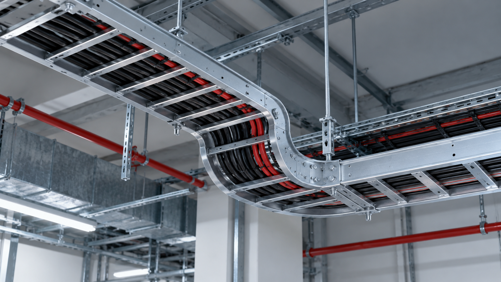
Choosing a cable tray involves more than comparing product dimensions and unit prices. Engineers and procurement teams also need to consider the installation environment, structural requirements, component compatibility and long-term maintenance needs.
A ZM perforated cable tray brings together zinc-aluminum-magnesium coated steel and a formed cable-support profile. In the ECTRAY design discussed here, stamped bottom reinforcement adds another structural feature to the perforated base.
Understanding how these features relate to project requirements makes the selection process more useful. This guide explains the product’s advantages and how they can contribute to a coordinated cable management system.
ZM refers to a zinc-aluminum-magnesium alloy coating on steel. The coating contributes to corrosion protection, while the formed steel profile provides the structure used to support cables.
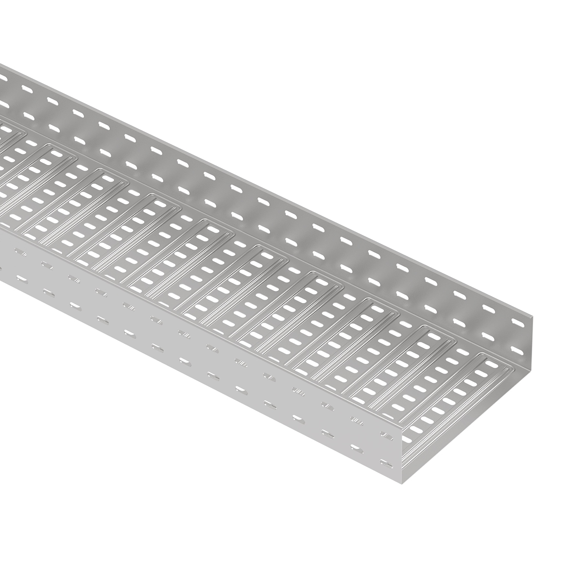
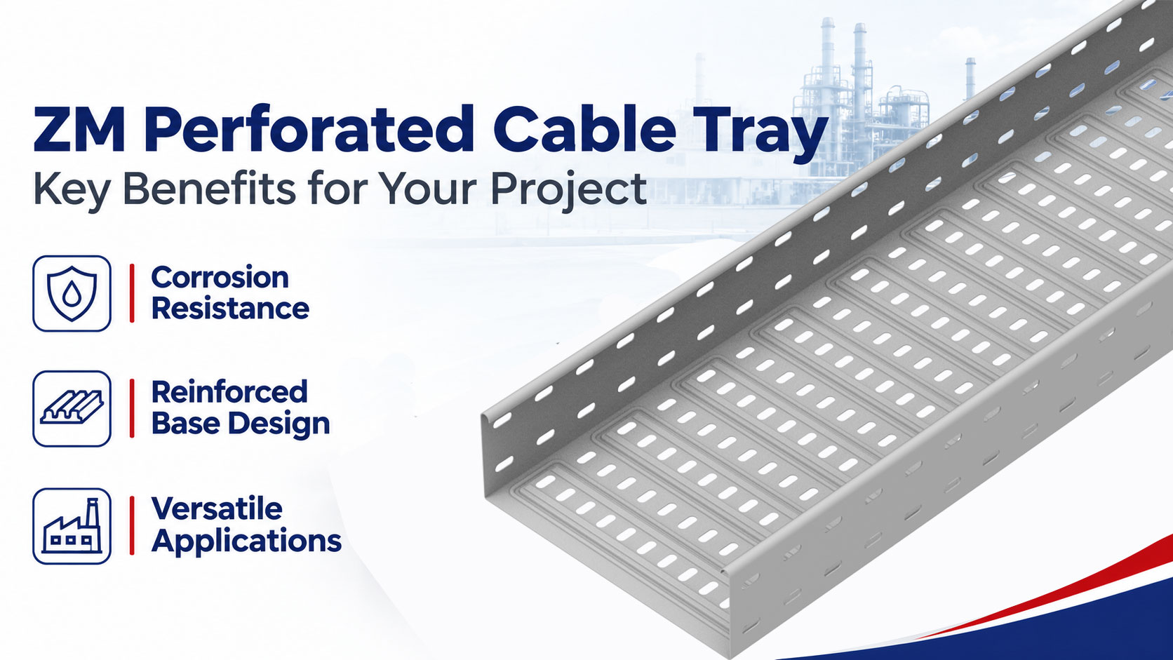
ECTRAY’s reinforced design incorporates a perforated base, raised sidewalls, folded edges and stamped bottom reinforcement.
These features address different aspects of product selection.
| Product feature | Function | Project consideration |
|---|---|---|
| ZM coated surface | Contributes to corrosion protection | Suitability for the installation environment |
| Stamped bottom reinforcement | Changes the base geometry | Structural performance of the selected configuration |
| Perforated base | Provides cable support with openings | Cable arrangement, exposure and route requirements |
| Folded edges | Form part of the section profile | Product geometry and accessory interfaces |
| Matching fittings and connections | Complete changes in direction and joints | Route coordination and purchasing scope |
The advantages of the product should be assessed together. A suitable surface option still needs an appropriate support arrangement, and a reinforced structure still needs compatible connections.
The ZM coating provides a protective metallic surface on the steel.
Protective corrosion products can form on the coated surface under relevant exposure conditions, helping to limit corrosion development. This makes ZM a coating option worth evaluating where corrosion protection is an important project requirement.
For buyers, the benefit is a material choice that can be assessed against the actual installation environment.
Review exposure to moisture, airborne salts, industrial contaminants and contact with other materials. The ZM designation alone does not establish suitability for every location.
A perforated tray includes more than uninterrupted flat surfaces. Cutting, punching and forming create edges and regions that deserve attention during material selection.
Protective corrosion products associated with ZM coatings can contribute to cut-edge protection under suitable conditions. This is relevant when assessing products that contain numerous processed features.
The project benefit is a more complete basis for reviewing corrosion protection: the assessment can consider surfaces and processed areas together.
Cut-edge protection should not be interpreted as a guarantee that exposed edges never develop rust. Product information should be relevant to the actual material, processing and environment.
When reviewing corrosion evidence, refer to ISO 9227 salt spray testing for the scope and limitations of the method. Salt spray results should not be used to predict outdoor service life.
ECTRAY’s design includes stamped reinforcement features in the tray base.
Forming changes the base geometry and can contribute to stiffness and resistance to local deformation. The effect depends on the reinforcement profile and its relationship to the complete tray section.
For a project team, this provides a reinforced configuration to evaluate against the required cable loading and support arrangement.
The reinforcement should be reviewed through the applicable drawings and performance information. It should not be treated as automatic proof of a particular load rating or longer support span.
A cable route needs straight sections, connections and fittings that work together.
Different tray widths, heights and lengths allow the product configuration to be coordinated with the cable arrangement and installation space. Matching bends, tees, reducers and connection components help define the complete route.
This supports clearer purchasing and drawing preparation. Instead of specifying only straight sections, the project team can identify the interfaces and components needed throughout the system.
Explore ECTRAY’s perforated cable tray range when preparing the required configuration.
A useful material decision begins with the site.
For an exposed rooftop, a sheltered service area and an industrial location affected by contaminants, the relevant conditions may differ substantially.
Selecting a ZM perforated cable tray with these conditions in mind helps the project team define a more appropriate material requirement.
This approach also improves communication with suppliers. Information about the exposure allows the proposed product to be reviewed against a specific application rather than a broad description such as “outdoor use.”
Stamped bottom reinforcement gives engineers a defined structural feature to include in their review.
The project benefit comes from evaluating that configuration against the required cable load and proposed support span.
Confirm the relevant product dimensions, material properties, loading method and support conditions. Check how tray self-weight, covers and other applicable loads are treated.
If performance values are calculated rather than tested, identify their basis and assumptions. This makes the information easier to assess during technical approval.
A reinforced product does not necessarily reduce the number of supports. That outcome requires confirmation through the project design and relevant performance information.
Route planning requires attention to turns, branches, transitions and equipment entry points.
A coordinated product schedule helps identify which components are required at each location. It also allows connection geometry and accessory compatibility to be reviewed before purchasing.
This can help reduce clarification requests and the risk of missing items.
The benefit depends on providing an accurate route drawing and checking the complete supply scope. Matching nominal sizes alone does not confirm every connection detail.
Corrosion protection is relevant to the maintenance plan.
Where the selected ZM product is suitable for the exposure, it can help address corrosion-related concerns within the cable support system. Inspection should still consider joints, fasteners, supports and areas where moisture or contaminants may collect.
The practical benefit is the opportunity to consider maintenance needs during product selection.
Avoid describing the system as maintenance-free. Its condition depends on the environment, installation and complete component arrangement.
The purchase price of straight tray sections is only one part of the project cost.
A meaningful comparison includes fittings, connections, supports, covers, documentation and any requirements associated with the selected system.
| Cost item | What to compare |
|---|---|
| Straight tray sections | Equivalent product configuration and quantities |
| Fittings | Required bends, tees, reducers and risers |
| Connections | Splice plates and specified fasteners |
| Supports | Approved supporting arrangement |
| Covers | Cover sections and fixing components where required |
| Documentation | Drawings and relevant product information |
| Maintenance | Access requirements and anticipated inspection needs |
A ZM perforated cable tray should therefore be assessed as part of a complete proposal.
Whether it provides a cost advantage depends on the project. A lower unit price does not establish a lower total installed or lifecycle cost.
Rooftop solar cable routes need coordination with photovoltaic equipment, roof conditions and maintenance access.
ZM perforated cable tray can be considered where its material characteristics and reinforced configuration meet the project requirements.
Review environmental exposure, cable arrangement, supporting structures and compatibility with other components.
Coordinate the route with drainage and designated access areas. Where a maintenance walkway is required, specify it separately from the cable tray.
Industrial projects can combine sheltered areas, outdoor routes and locations affected by process-related contaminants.
The suitability of ZM should be reviewed for each relevant exposure zone.
A reinforced tray configuration can then be evaluated against the cable load, available support locations and route geometry.
This links the material and structural decisions to the actual installation rather than assuming one configuration suits the entire facility.
Commercial projects may use cable trays in equipment areas, service spaces and external routes.
Product dimensions and matching fittings can help coordinate the cable route within the available space.
Material selection should still reflect the actual environment. Indoor locations may experience condensation or other exposure that needs to be considered.
Provide the project location and describe the exposure.
Identify moisture, salt, industrial contaminants and contact with other materials where relevant. This gives the supplier a clearer basis for reviewing the proposed product.
Prepare a cable schedule with cable types, quantities, outside diameters and weights.
Select the tray dimensions according to the approved arrangement and installation space. Confirm whether the stated dimensions are overall measurements or internal clearances.
Include planned future additions where they are part of the project requirements.
Review performance information for the actual configuration and supporting arrangement.
Section length and support span are different measurements. A manufactured tray length does not establish an allowable distance between supports.
The stamped reinforcement is one part of the structural assessment, together with the complete section and connection conditions.
IEC 61537 — Cable Tray Systems and Cable Ladder Systems
Confirm the required fittings, splice plates, supports, covers and fasteners.
Check their dimensions, materials and connection details. Do not assume that every accessory automatically has the same surface specification as the tray.
A complete component schedule makes the quotation and technical review easier to compare.
ECTRAY offers ZM perforated cable tray with stamped bottom reinforcement for project-based selection.
To review a configuration, share your route drawing, BOQ and installation conditions.
| Information to provide | Purpose |
|---|---|
| Project location and exposure | Review material suitability |
| Required dimensions | Define the tray configuration |
| Cable schedule | Assess cable arrangement and loading inputs |
| Proposed support conditions | Review span and supporting requirements |
| Route drawing | Identify turns, branches and transitions |
| Accessory schedule | Define the complete supply scope |
| Quantities and delivery requirements | Prepare the quotation |
Contact ECTRAY to discuss a ZM perforated cable tray configuration for your project.
It combines a corrosion-protection coating option with a perforated steel cable-support structure. Suitability depends on the actual environment and complete product configuration.
It changes the base geometry and can contribute to stiffness and resistance to local deformation. Its performance should be reviewed as part of the complete tray section.
No. Cut-edge protection mechanisms do not guarantee corrosion-free performance under every exposure condition.
Yes, where the selected product and supporting system are suitable for the roof conditions, environmental exposure and cable requirements.
No. The proposed span must be confirmed using relevant performance information and the project design.
Not necessarily. Compare equivalent product configurations, complete supply scopes and project requirements.
No. Inspection needs should be defined for the environment and complete assembly, including connections, supports and fasteners.
Provide the route drawing, required dimensions, ca