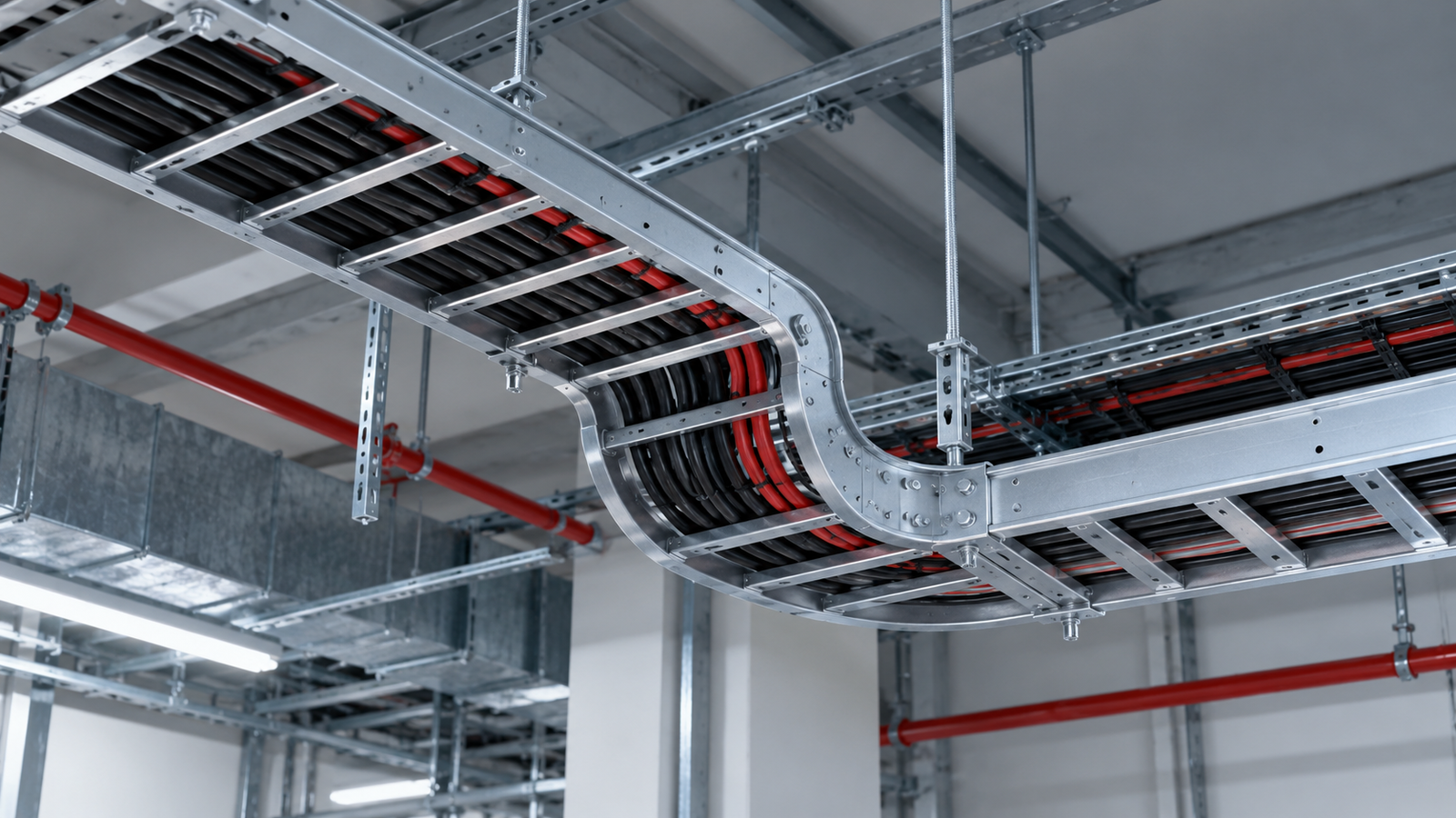
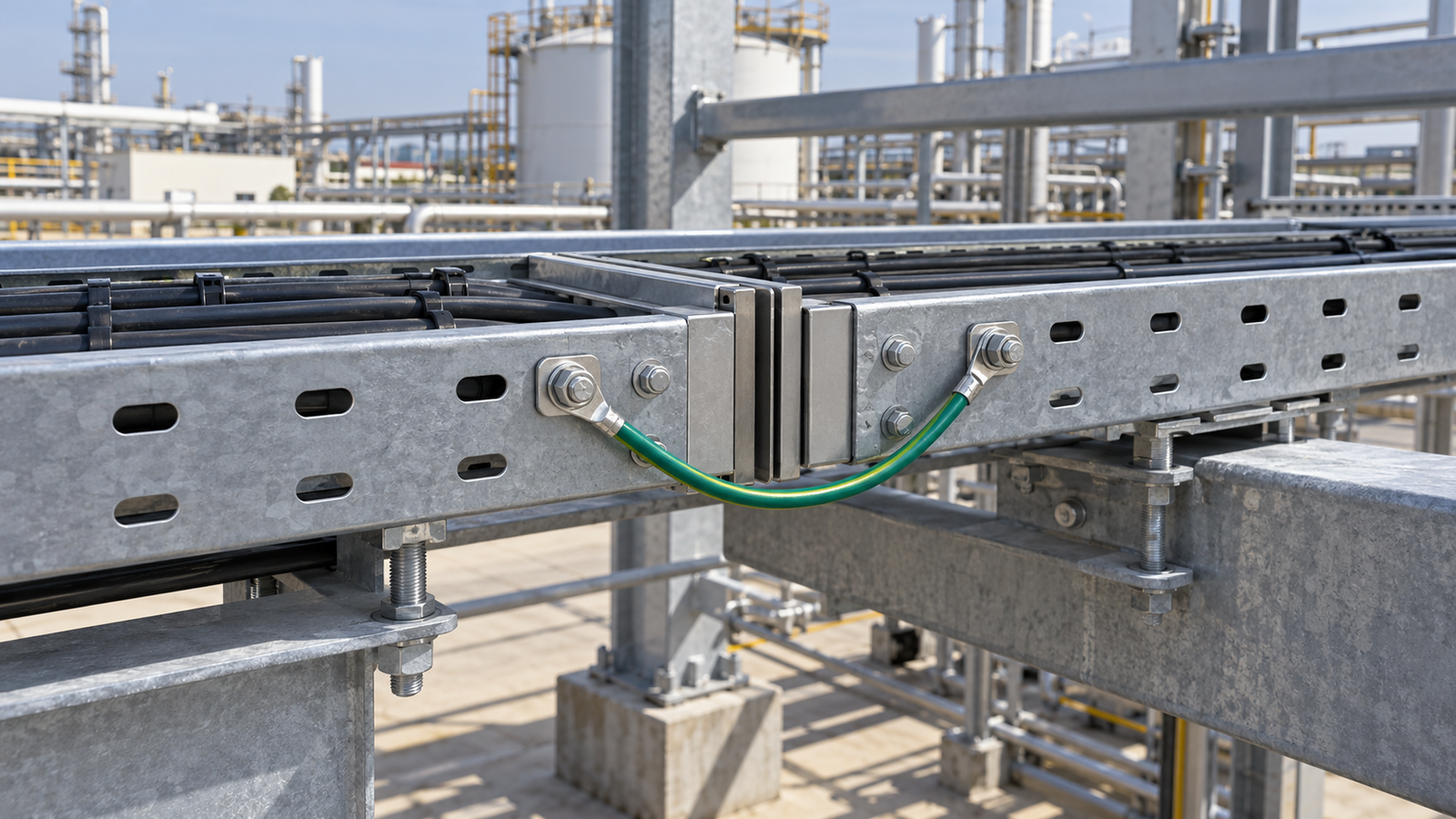
A cable ladder 90 bend is a fitting that turns a ladder route through a right angle. That description identifies the change in direction, but it does not specify the fitting you can safely order. The turn might be horizontal, an inside vertical rise or an outside vertical drop. Its radius must suit the cables; its width, rails and connectors must match the selected ladder system; and its support must be checked as part of the installed route.
The quickest way to get the wrong bend is to quote only “90 degrees” on a schedule. A supplier can satisfy the angle while offering the wrong plane of travel, an unsuitable radius or a connection that does not fit the adjoining straight section. The error may not become visible until installers reach the corner. Even then, forcing a sharp turn or improvising a splice is not an acceptable design solution.
This guide works from the route drawing outward. It explains the three main turning geometries, how to evaluate radius and loading, and what to ask a manufacturer to document. OBO, ABB and SITIE catalogues illustrate the issues, but their details remain product-specific. ECTRAY's public ladder family is relevant to a project enquiry; it does not by itself establish that a particular 90-degree fitting is available or suitable.
Mark the route's centreline on plan and elevation drawings before selecting a product. A corner visible on plan calls for a horizontal change in direction; a rise or drop visible in elevation requires a vertical fitting. Identify the cable entry and exit directions, available clearance, obstacles, support points and access for pulling or laying cables. A 90-degree angle says nothing about whether those conditions can be met.
Then locate the cables that govern the turn. A large power cable or sensitive fibre assembly may need more space than the smallest cable in the schedule. The designer should check cable-manufacturer instructions for minimum bending radius during installation and in service, as applicable. The Cable Tray Institute says the largest required cable bending radius controls the tray fitting radius; ABB's technical guide makes the same practical distinction. Do not substitute a standard catalogue radius for that check.

Draw the route in plan and elevation before choosing the bend.
Finally, define what happens immediately before and after the bend. A corner may meet a tee, riser or piece of equipment within a short distance. If the straight sections cannot be supported or accessed as intended, a nominally correct bend may still be wrong for the whole route. Record the geometry first; only then compare compatible fittings.
A horizontal 90-degree bend changes direction in a horizontal plane. On a plan drawing, the ladder turns left or right while staying at roughly the same level. Zexin's horizontal elbow product page distinguishes left and right versions and describes a purpose-made 90-degree component. Those are features of that specific range, not universal properties of every ladder system.
An inside vertical bend and an outside vertical bend change elevation in opposite ways. The distinction depends on which side of the ladder the cables follow through the turn. A drawing should show the cable path, not merely label a fitting “vertical 90.” SITIE's external vertical bend and Legrand's inside vertical fitting pages demonstrate that catalogues separate these configurations. Treat the names on a purchase schedule as prompts to check the manufacturer's geometry, not as interchangeable parts.
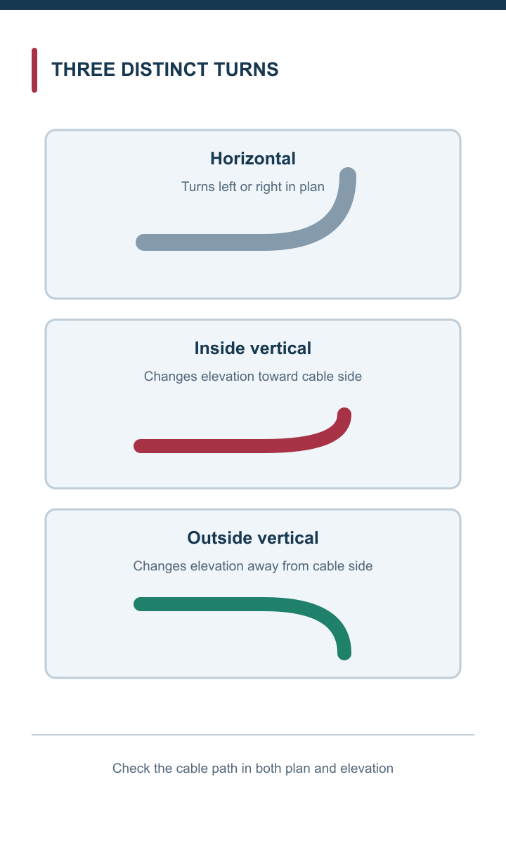
Horizontal and vertical fittings solve different turns.
An articulated or adjustable fitting may connect horizontal and vertical sections or accommodate an offset. OBO's mounting instructions describe such a component assembled from bend elements. That flexibility does not remove the need to verify the resulting radius, joints, supports and available clearance. A dimensioned section view is often more useful than a thumbnail image of the fitting.
Angle and radius answer different questions. The angle tells you how far the route changes direction. Radius describes the curve the cables follow around that change. Two 90-degree elbows may have different footprints and very different cable paths. A compact elbow can appear attractive in a congested ceiling but still impose an unacceptable cable bend.
Start with the cable schedule and the cable manufacturer's installation instructions. Identify the largest applicable minimum radius, allowing for the actual cable construction and whether the value applies during pulling or after installation. Next obtain the proposed fitting's dimensional drawing. Check which radius the manufacturer quotes—inner, centreline or another reference—and compare the actual cable path to the requirement. A bare number without a reference line is not enough for sign-off.
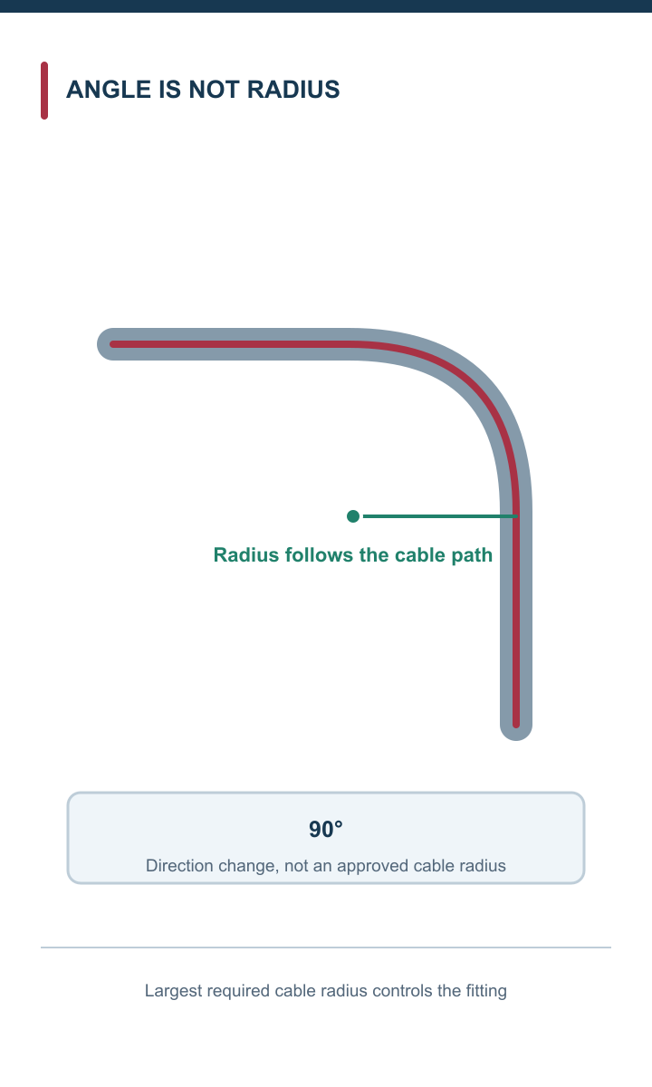
The cable path and its required radius govern the fitting.
OBO and Zexin show product-specific radii in their documents, but neither establishes a universal radius for a cable ladder 90 bend. If the available fitting is too tight, enlarge the route, choose a different fitting family or redesign the transition. Do not claim that a 90-degree angle alone protects the cable. Record both the governing cable requirement and the verified fitting geometry on the project drawing.
A bend has to join the ladder that feeds it. Check nominal width and side-rail height, but do not stop there. The rail profile, rung arrangement, splice-hole pattern, connector design and material thickness may differ between families that share the same headline dimensions. OBO's manual documents specific connectors and bend assemblies; its connection method is evidence for the OBO system, not a generic installation detail for every manufacturer.
Ask the supplier for the fitting's exact part number and a drawing showing how it meets the selected straight section. Include splice plates, fasteners, covers and any expansion or transition components in the bill of materials. If a route changes from ladder to a different tray type, name that transition and its support method rather than relying on a field-made joint.
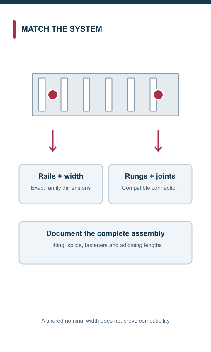
Nominal width alone does not establish family compatibility.
Fit also matters where the bend approaches a wall or support. A wider-radius elbow occupies more space than its nominal ladder width suggests. Dimension the outside envelope and the usable inside path. A clash discovered before ordering is a drawing revision; the same clash discovered during installation can become an expensive improvised detail.
The longest straight span is not an adequate support plan for a bend. Fittings introduce joints and curved sections whose behavior may differ from the tested straight length. The Cable Tray Institute notes that fittings may not satisfy straight-section strength assumptions unless supported according to the applicable installation guidance or the manufacturer's instructions. ABB's guide illustrates horizontal and vertical fitting support arrangements and alternatives, rather than one universal distance for all products.
Show each support near the turn on the layout. Confirm the allowable location of joints, the required distance from the fitting and whether an additional support is needed at its midpoint. Review both incoming and outgoing straight sections; a properly supported elbow does not rescue an overstretched adjoining run. Check hanger, bracket and building attachment capacities against the actual installed load.
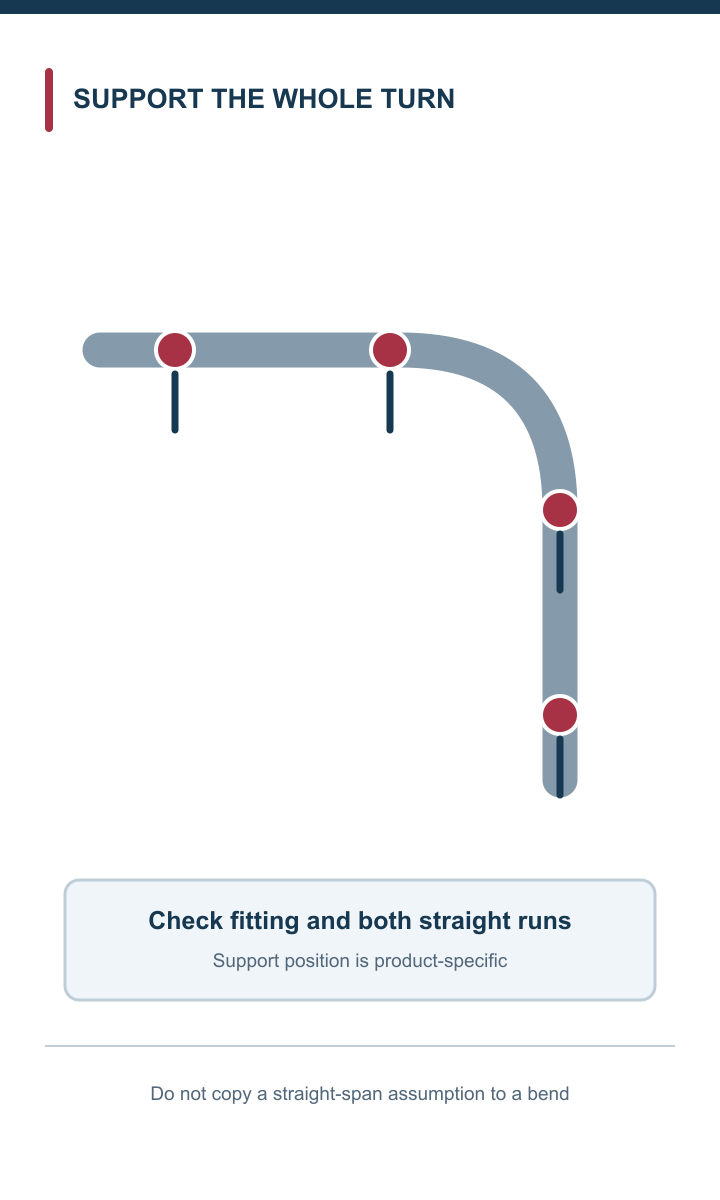
Support the fitting and both neighbouring straight sections.
Where the bend rises or drops, cable weight and restraint can change the force path. The responsible designer should verify the ladder, support and cable restraint together. Do not copy a manufacturer's example support spacing from another range into the project specification. Ask for an installation drawing tied to the exact proposed components.
Cable ladder loads are not set by visual size alone. Calculate the mass of the current cables, include the approved future allowance and account for any project-specific concentrated load. Then compare those demands with the proposed ladder system's rated span and the fitting and support data. The Cable Tray Institute describes cable weight as a controlling input to the load the supports must carry.
Be precise about what a published load table covers. A straight section, a 90-degree fitting and a supporting bracket may have different evidence and conditions. The rail may be rated at one support spacing while an elbow requires closer support. A cover, wet environment or heavy cable bundle can also change the installed assembly. Ask the manufacturer to identify the exact test or engineering basis used for the quoted configuration.

Use actual cable weight and exact-assembly performance data.
If the data do not cover the proposed bend, leave the point open for the design reviewer. Do not interpolate from the nearest width or assume that a matching finish implies a matching rating. Document the checked load, support pattern and exceptions so that a later route change triggers a deliberate recheck.
A complete bend is also a series of connections. The supplier should identify the splice plates, fasteners and any required bonding components, and explain how the fitting joins the neighbouring ladder sections. OBO's instructions discuss connectors and equipotential bonding for its system. That is a reminder to examine the entire assembly, not a reason to copy its method into an unrelated product family.
For metallic systems, the designer must determine the project's electrical continuity and bonding requirements under the applicable code and installation standard. A bolted joint may have a documented continuity method, or the design may require a jumper. Do not infer compliance from a photograph of two touching rails. Check how a coated, insulated or dissimilar-material component affects the chosen arrangement.
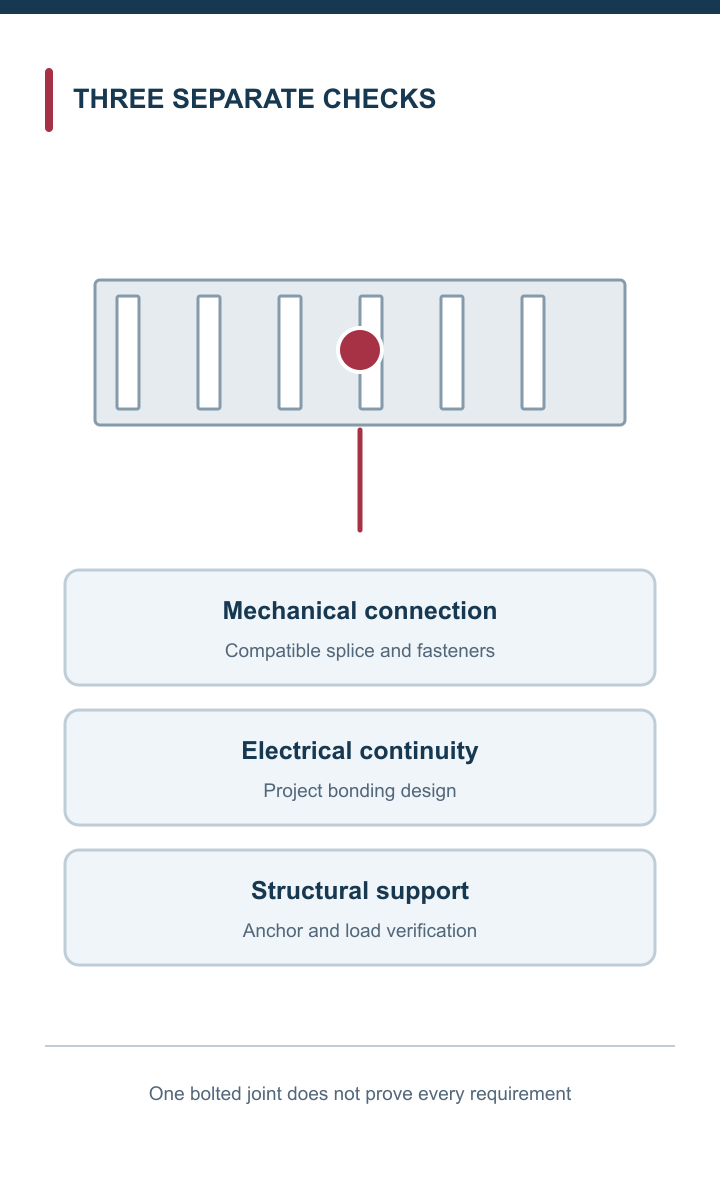
A bolted joint does not prove every installation requirement.
The same documentation should reach the installer. A specification that says only “bond as required” without identifying the product instructions, responsible design and verification method is hard to execute consistently. Record which joints were considered and which manufacturer evidence supports the solution.
A bend can be geometrically correct and still have the wrong environmental specification. Indoor dry corridors, external roofs and washdown or coastal areas call for different material and finish decisions. The bend, straight sections, connectors, fasteners and supports should form a compatible system under the selected exposure strategy.
ABB's technical guide treats material and finish selection as a separate part of cable-tray design. Follow that separation here. Choose the turn's geometry to protect and route the cables; choose the material and finish against the actual exposure and project life requirements. A hot-dip galvanized component, stainless component and powder-coated component are not interchangeable merely because each is sold as a 90-degree elbow.

Choose geometry and environmental finish independently.
Ask for a finish schedule covering fittings and small accessories, not just straight ladder. Where a cut edge, site modification or dissimilar-metal connection is proposed, obtain the manufacturer's treatment instructions and the designer's acceptance. An exact product drawing should make the environmental choice traceable to the offered part numbers.
A prefabricated 90-degree fitting suits a route whose geometry is known and whose compatible family has the required radius and support details. It can simplify installation because the curve, joints and part number are defined in advance. Its limitation is that it occupies a fixed envelope; a congested site may make the standard radius or orientation impossible.
An articulated fitting can handle an offset or a transition between planes, depending on the manufacturer's range. OBO's mounting instructions describe how an articulated bend uses multiple elements and connectors. That does not make a segmented turn a free-form substitute for a qualified elbow. The final assembled path still needs an acceptable cable radius, compatible joints, support, fastening and continuity detail.
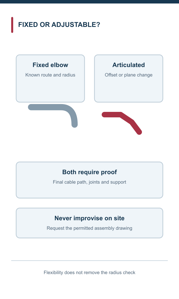
Adjustability does not remove radius, connection or support checks.
When proposing an adjustable bend, request its permitted configurations and installation drawing. Show the intended angle and resulting cable path on the project drawing. If a site team would have to guess how many elements or where to support them, the design is not ready for purchase. Select flexibility only when the evidence covers the actual assembled route.
| Choice | When it helps | Check before approval |
|---|---|---|
| Fixed 90-degree elbow | Route and radius are known | Exact radius, envelope, joints and supports |
| Articulated fitting | Offset or plane transition is needed | Permitted assembly, final cable path and each connection |
A useful specification makes the route reviewable by someone who was not in the original design meeting. Put the following items on a drawing or fitting schedule, and mark any unresolved item as an exception rather than leaving it to interpretation.
| Check | Record for the proposed bend |
|---|---|
| Route geometry | Horizontal, inside vertical or outside vertical; approach, exit and clearance |
| Cable constraint | Governing cable type and minimum bend radius, with the reference used |
| Ladder compatibility | Exact family, width, side-rail details and connection method |
| Loading | Cable weight, growth allowance, fitting and support evidence |
| Supports | Locations around the bend and adjoining straight sections |
| Environment | Material, finish and treatment of fittings and fasteners |
| Electrical detail | Project-required continuity and bonding method |
| Procurement | Part numbers, drawings, accessories and exceptions |
Do not use this table as a substitute for the manufacturer's installation guide or a qualified design review. Its purpose is to expose missing assumptions before a bend becomes an on-site surprise.

Resolve all six specification inputs before approving a fitting.
ECTRAY's public catalogue identifies cable ladder as a product family, which makes it a relevant supplier to ask about a planned ladder route. The catalogue alone does not verify the availability, dimensions, radius or rating of an exact cable ladder 90 bend. A useful enquiry therefore begins with the route and cables rather than asking simply for “a 90-degree elbow.”
Send the plan and elevation drawings, cable schedule, governing bend-radius requirement, preferred ladder width and family, loading assumptions, support layout and environmental finish requirements. State whether the turn is horizontal, inside vertical or outside vertical. Ask ECTRAY to return exact part numbers, fitting and connection drawings, compatible supports, product data and any exceptions to the proposed specification.
If the standard range does not suit the route, invite a documented alternative for engineering review. That keeps the commercial discussion productive without presenting an unverified catalogue claim as an approved installation.
Include the proposed installation method and a clear list of items requiring the designer’s confirmation.
Four shortcuts cause most specification problems. First, choosing by angle alone can produce a fitting in the wrong plane or with a radius too small for the cable. Second, matching only nominal width can conceal incompatible side rails and splices. Third, copying a straight-section span to the corner can leave the fitting inadequately supported. Fourth, assuming that a metal joint is electrically continuous can bypass the project's bonding design.
There are quieter mistakes too. A bend may be ordered with the right finish while its brackets and fasteners have a different exposure rating. A route may show the elbow but not the clearance needed to place cables through it. A change from prefabricated to articulated hardware may alter the support and connection details without an updated drawing.
These are not reasons to avoid a ladder bend. They are reasons to make its selection a coordinated design decision. A short review of the actual cable schedule, fitting drawing and installation instructions is more useful than a long list of generic product advantages.
Specify a cable ladder 90 bend by the route it serves, not by the right angle in its name. Confirm whether the turn is horizontal or vertical, compare the fitting's actual cable path with the governing minimum bend radius, and match the bend to the exact ladder family. Then verify load, nearby supports, connectors, bonding and finish for the complete installed assembly.
The manufacturer examples in this guide show why those checks matter; none supplies a universal 90-degree bend specification for another brand. For an ECTRAY project, send a dimensioned route drawing and cable schedule, then request the exact compatible fitting and its evidence. Keep any unsupported dimension or rating open until the supplier and responsible designer resolve it. The result should be a bend that can be installed and reviewed with confidence, not merely a part whose catalogue description contains the right angle.