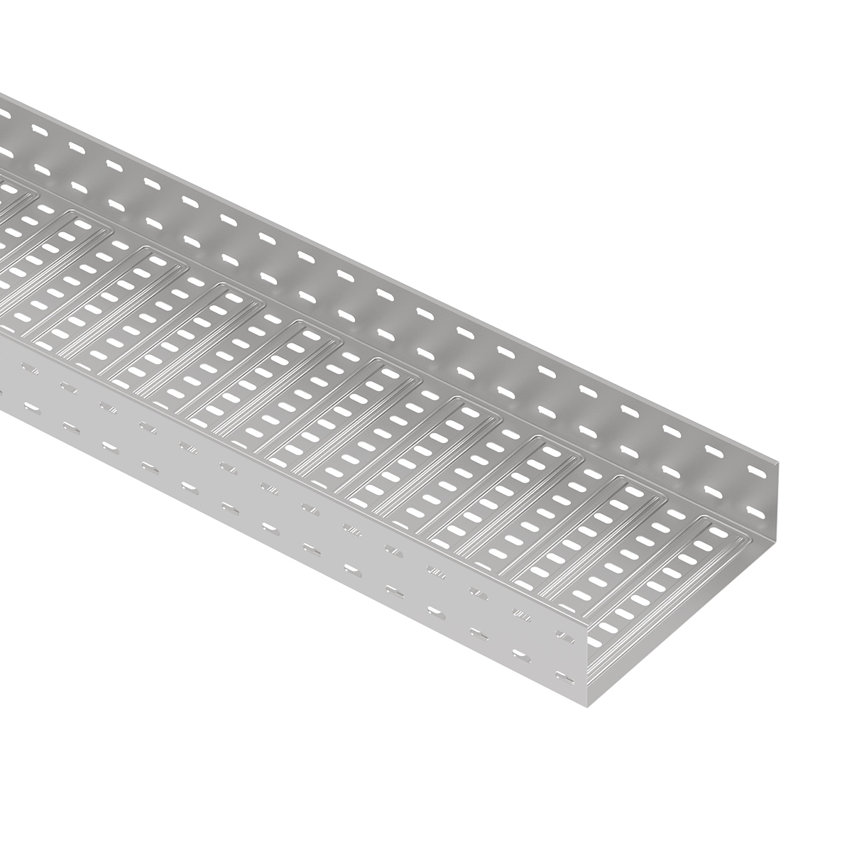
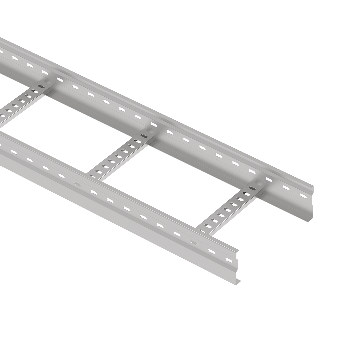
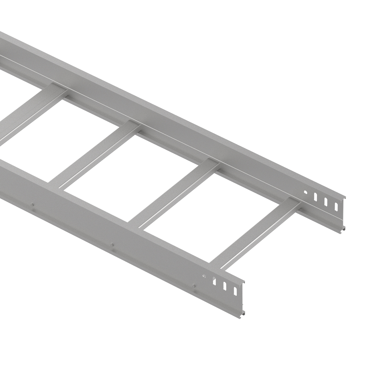
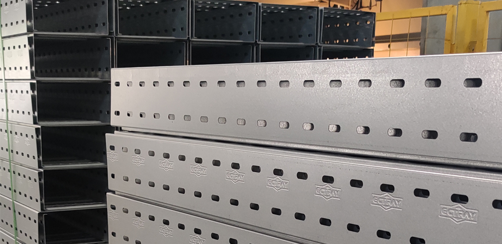
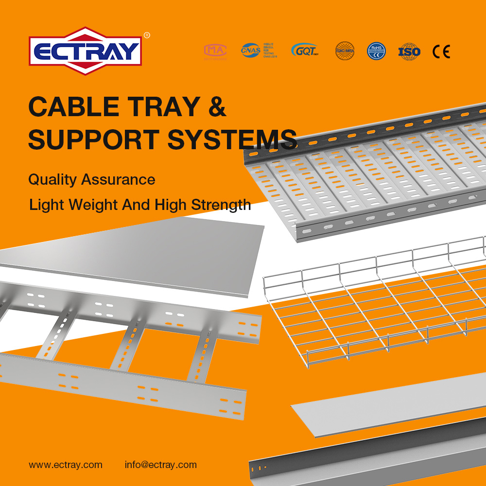
A reinforced perforated cable tray uses a formed profile or other defined strengthening features to support its structural performance. In a tray with stamped bottom reinforcement, the base includes shaped ribs or contours rather than remaining flat between its perforations.
This difference matters when comparing cable tray designs. Material thickness is an important specification, but it does not describe the complete structure. Tray width, sidewall height, edge profile, perforation pattern, connections and support spacing also influence performance.
For engineers, contractors and procurement teams, the practical question is how the proposed tray configuration will perform under the required cable load and installation conditions.
This guide explains how stamped bottom stiffening works, compares standard and reinforced construction, and outlines the information needed to assess thickness, support span and working load.
A reinforced perforated cable tray combines a perforated cable-supporting base with defined structural strengthening features. These may include stamped bottom profiles, formed sidewalls, folded edges or other features specified by the manufacturer.
The term “reinforced” should identify an actual design feature. It does not, by itself, establish a particular working load or support span.
A standard perforated cable tray generally consists of a formed steel base, sidewalls and openings arranged along the section. Depending on the design, the sidewalls may include folded edges or other profile details.
Here, “standard flat-base construction” means the tray does not have additional stamped bottom stiffening. The base can still contain perforations.
Installed cable weight acts on the base and is transferred through the tray section, connections and supports into the supporting structure. Performance therefore depends on the assembled system.
When comparing products, review the section drawing rather than relying only on a photograph or a nominal width and height. Two trays with the same external dimensions can have different edge profiles, hole layouts and connection details.
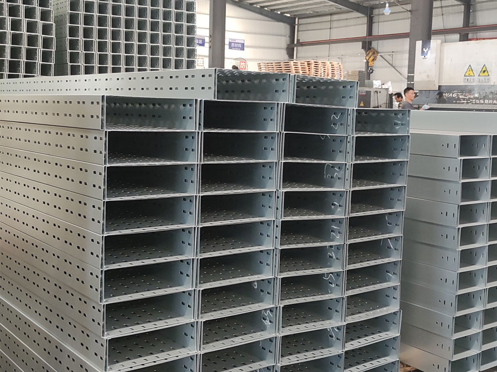
Stamped bottom reinforcement introduces raised or recessed contours into the tray base. These features change its geometry and can influence how the base responds to loading.
Perforating and forming are different operations. Perforating creates openings in the sheet. Forming shapes the sheet into a profile.
A reinforced tray may incorporate both: openings for the required cable support design and formed contours intended to improve structural behavior.
The reinforcement should be described through measurable details, including profile depth, width, spacing and direction. These details provide a clearer basis for comparison than a general claim such as “extra strong.”
A formed sheet behaves differently from a flat sheet because its geometry changes the way it resists deformation.
However, the effect depends on the shape and loading direction. A feature that improves local base behavior may not produce the same improvement in the tray’s longitudinal bending performance.
A flat sheet can bend relatively easily across an unsupported area. Forming ribs or contours changes the sheet geometry and can increase resistance to bending in particular directions.
The resulting behavior depends on the reinforcement dimensions and its relationship to the load and supports.
For example, a profile extending across the tray width may affect local base behavior differently from a profile running along its length. The surrounding sidewalls and the way the base connects to them also matter.
For this reason, reinforcement should be assessed within the complete tray section. The presence of a stamped profile alone does not establish how much additional cable load the finished product can carry.
Local deformation, material yielding and buckling describe different structural responses.
Local deformation refers to a change in shape around a loaded area. Yielding occurs when material stress reaches the relevant yield condition. Buckling is a loss of structural stability associated with compressive stress.
Stamped profiles can change the areas over which the base deforms and alter potential buckling modes. The extent of any improvement depends on the actual geometry, material properties, loading and constraints.
An assessment should therefore consider more than a single result. Working-load behavior may involve stress, deflection, local stability and connection performance, with different criteria governing different configurations.
Reinforcement direction should match the structural behavior being assessed.
The tray base supports cables across its width, while the complete section also carries loads between supports along its length. These are related but distinct aspects of the design.
A bottom feature that reduces local panel deformation does not automatically justify increasing the longitudinal support span. Sidewall behavior, splice details and support conditions may still govern the installation.
Product comparisons should identify whether the evidence relates to a local base panel, a complete straight section or an assembled system with joints.
A useful comparison starts with the actual product configuration and the performance required by the project.
ECTRAY offers trays without stamped bottom stiffening and trays with stamped bottom reinforcement within the following thickness ranges.
| Comparison Item | Without Stamped Bottom Stiffening | With Stamped Bottom Reinforcement |
|---|---|---|
| Base geometry | Perforated base without additional stamped stiffening | Perforated base with a formed stiffening profile |
| Available material thickness | 0.6–2.0 mm | 0.6–1.5 mm |
| Example width × height | 300 × 50 mm | 300 × 50 mm |
| Example material thickness | 0.8 mm | 0.8 mm |
| Example section length | 3000 mm | 3000 mm |
| Support span considered for evaluation | 1500 mm | 1500 mm |
| Working load | Requires configuration-specific verification | Requires configuration-specific verification |
The example dimensions establish a basis for comparison. They do not constitute a published working-load rating at a 1500 mm support span.
To isolate the effect of bottom reinforcement, compare both designs under equivalent conditions.
These should include the same material properties, actual sheet thickness, external dimensions, support arrangement and applied cable load. Differences in each product’s self-weight should also be accounted for.
The load definition needs particular attention. A force applied separately to several selected faces can differ from one total force distributed across those faces. The final applied force and its distribution should be checked.
Connections, constraints and evaluation criteria should also be consistent. Otherwise, a difference in results may reflect the analysis setup as well as the product geometry.
A reinforced configuration is worth evaluating when a project needs better control of local base deformation or when the design team is comparing different profiles and thicknesses.
It may also be considered during an effort to optimize material use, handling weight or manufacturing configuration.
These objectives need supporting performance data. A reinforced tray should not automatically be assigned to a higher load category, and a standard tray should not automatically be excluded from a demanding application.
The selection should follow the verified performance of the proposed configuration under the required installation conditions.
Buckling simulation can help engineers understand potential instability and compare structural designs.
Its usefulness depends on the model, assumptions and interpretation. A simulation result should always be connected to the specific question the analysis was designed to answer.
A comparative study can show how changing a bottom profile affects a modeled buckling mode under defined conditions.
It can help identify vulnerable regions, compare alternative shapes and guide further design work. For product development, this provides information before selecting configurations for more detailed analysis or physical testing.
A local sample model has a limited scope. It may examine a base region without representing the full longitudinal span, actual joints or complete support arrangement.
The study description should clearly state what was modeled and which parts of the installed system remain outside its scope.
A linear buckling load factor relates a modeled reference loading pattern to an estimated critical condition for a particular mode.
It is a dimensionless result, rather than a load expressed in kg/m. Its sign is relevant: a negative factor relates to the reversed reference loading pattern.
Buckling mode shapes illustrate the form of potential instability. Their displayed amplitudes are normalized and should not be interpreted as actual working-load deflections.
Consequently, a ratio between two buckling factors should not automatically be described as the same ratio between allowable cable loads.
Actual service deflection requires an appropriate static analysis or load test.
A local buckling comparison does not, on its own, establish:
Before publishing performance claims, review material assignments, force definitions, constraints, mesh adequacy and the relevant modes.
For a project requiring a documented working load, the assessment must cover the offered configuration and the applicable performance criteria.
Thickness influences structural behavior, but it is one part of a larger design.
A comparison based only on millimeters of steel can overlook profile efficiency, local weaknesses and connection performance.
Sidewall height and edge geometry contribute to the behavior of the complete section between supports.
A folded edge changes the section geometry and may affect local stability. Tray width influences the area of the base supporting cables and the way loads reach the sidewalls.
Two trays with identical width, height and thickness can therefore perform differently if their detailed profiles differ.
Dimension tables should be supported by section drawings and working-load data for the configuration being supplied.
Perforations remove material and change the remaining load paths through the base.
Hole size, spacing, orientation and position relative to bends or reinforcement features can influence local behavior. The remaining material between openings also matters.
Stamped bottom geometry should be reviewed together with the perforation layout. Comparing a reinforced and an unreinforced tray requires more information than whether one has visible ribs.
A drawing should identify the features that affect the assessment, including any changes between standard production models.
Loads pass through the tray system into brackets, hangers and the supporting structure.
Splice plates, fasteners, joint locations and fixing details can affect system behavior. A straight section with adequate capacity still requires suitable joints and supports.
Fittings and transitions may need support arrangements that differ from those used on straight runs. Their installation should follow the relevant system instructions.
Where a load table is provided, check the connection and support assumptions behind it before applying the values to a different layout.
Section length and support span describe different dimensions.
A 3000 mm tray section may be installed with supports at shorter intervals. If supported at both ends and at its midpoint, it forms a different structural arrangement from the same section supported only at its ends.
Working-load selection must also consider the applicable deflection requirements. A configuration can have sufficient strength while exceeding a serviceability limit.
The relevant question is therefore: what load can the specified assembly carry at the proposed span while meeting all required criteria?
A thinner reinforced tray may be evaluated as an alternative, but substitution requires evidence for the intended installation.
Neither thickness nor a single simulation factor provides a reliable conversion between two products.
Compare the proposed configurations at the same support span and loading conditions.
The review should address working load, deflection, local stability, connection behavior and any relevant concentrated loads.
Material properties and actual thickness should match the supplied products. If forming-related material changes are included in the analysis, they need a documented basis; they should not be assumed from the manufacturing process alone.
Where the evidence is incomplete, request further analysis or testing rather than assigning an equivalent thickness.
A substitution affects more than the straight tray section.
Check whether the proposed thickness and profile remain compatible with splice plates, fittings, covers, fasteners and supports. Field cutting and other permitted modifications should also be considered.
Corrosion protection and project documentation remain separate approval requirements.
A thinner option is suitable only when the complete proposed system meets the specified mechanical, environmental and installation requirements.
A clear specification identifies both the product geometry and the conditions under which it must perform.
The following checklist helps suppliers and project teams prepare a meaningful technical comparison.
| Required Information | Details to Provide |
|---|---|
| Cable schedule | Cable types, quantities, diameters and weight per meter |
| Future additions | Defined allowance for additional cable weight and space |
| Tray dimensions | Width, sidewall height and section length |
| Material | Actual material grade and relevant properties |
| Material thickness | Specified base metal thickness and applicable tolerances |
| Reinforcement details | Profile dimensions, direction and spacing |
| Perforation layout | Hole dimensions, pattern and position |
| Support layout | Span, support type, fixing method and joint locations |
| Accessories | Fittings, covers, dividers, connections and supports |
| Environment | Moisture, outdoor exposure, coastal salt or chemicals |
| Surface protection | Coating designation and other project requirements |
| Performance evidence | Working-load data, deflection criteria and relevant reports |
The working-load documentation should state whether the published value represents an additional payload or includes the tray’s self-weight.
Covers and accessories should be accounted for on the same basis. Any concentrated or environmental loads require an appropriate assessment rather than being treated automatically as ordinary cable load.
For procurement, request data that matches the offered width, height, thickness, material, reinforcement and support conditions.
ECTRAY provides perforated cable tray configurations with different dimensions, material thicknesses, surface finishes and bottom profiles.
For projects considering reinforcement, the review should connect the proposed structure to cable load, support span, route layout and documentation requirements.
Explore ECTRAY’s perforated cable tray range to review product options.
Send your BOQ, cable schedule, route drawings, proposed support span and installation environment. Our team can help review tray dimensions, material thickness, bottom reinforcement, fittings and the information required for project evaluation.
Contact ECTRAY to discuss your cable support requirements and request a project quotation.
It is a perforated cable tray with defined strengthening features, such as stamped bottom contours or formed profiles. The reinforcement should be identified in the product drawing, and its performance verified for the intended configuration.
The effect depends on the reinforcement geometry, loading direction and complete tray design. Improving local base behavior does not automatically produce the same improvement in overall working load or allowable support span.
Possibly, but this requires a comparison of the actual configurations. Working load, deflection, stability, connections and installation conditions must meet the project requirements. Thickness alone cannot establish equivalence.
No. Buckling analysis estimates instability under defined modeling conditions. Safe working load requires the applicable assessment of strength, stability, deflection and other relevant criteria for the supplied system.
No. Section length is the length of the manufactured piece. Support span is the distance between adjacent supports. A 3 m section can be installed with intermediate supports, subject to the approved design and installation instructions.
A linear buckling mode image shows the shape of potential instability using normalized amplitudes. It does not show actual working-load deflection. Use an appropriate static analysis or load test to assess that value.
Request product drawings, material and thickness specifications, reinforcement details, working-load and support-span data, installation instructions and relevant test documents. Confirm that their scope matches the product being offered.