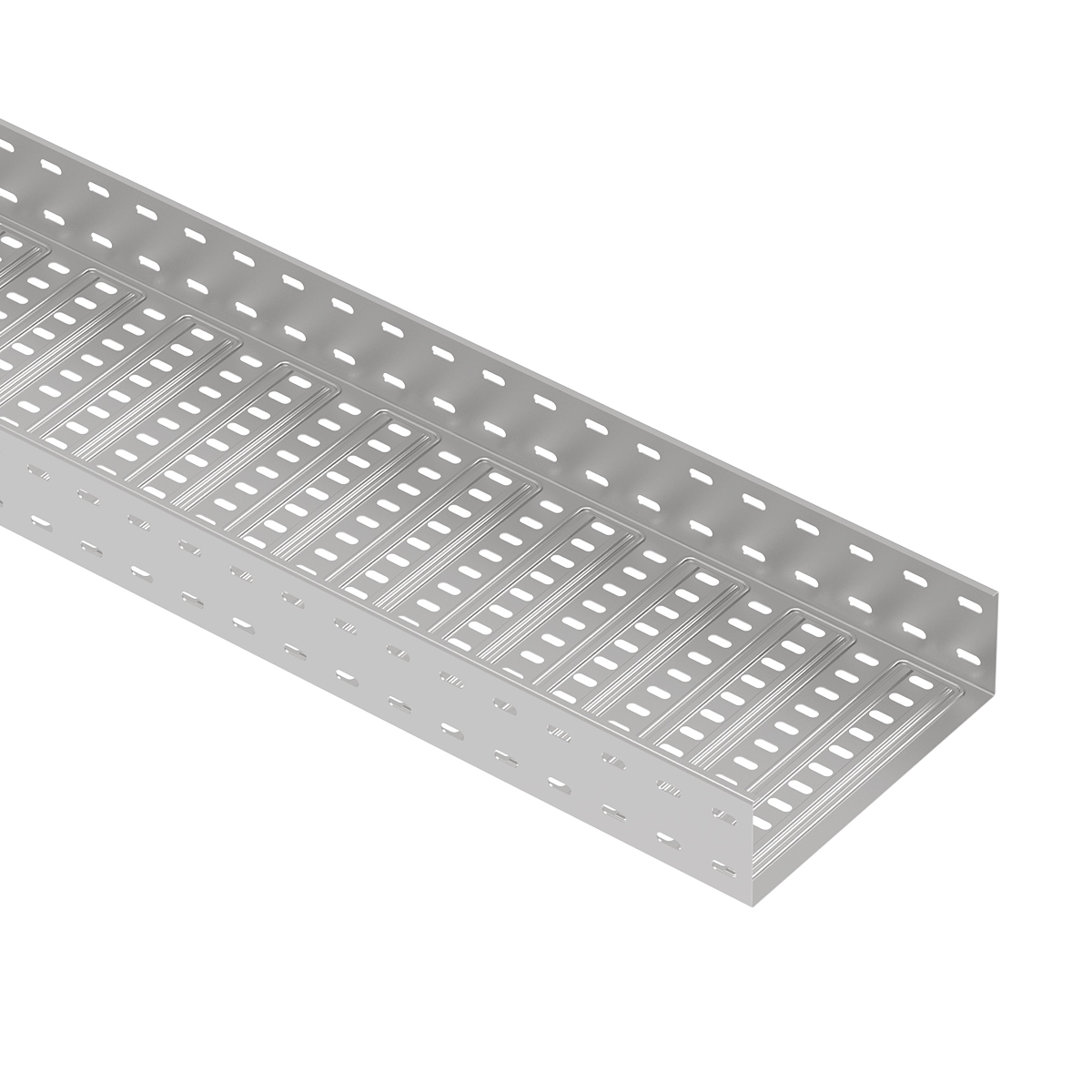
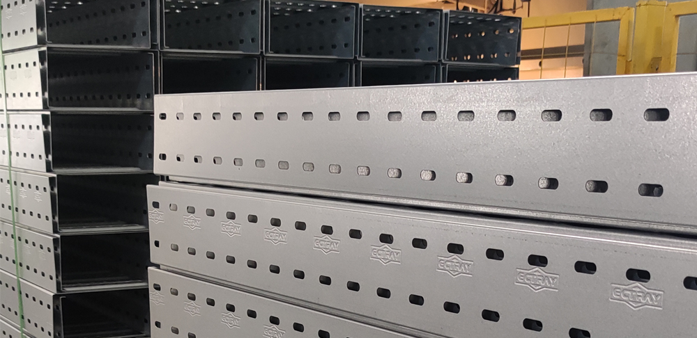
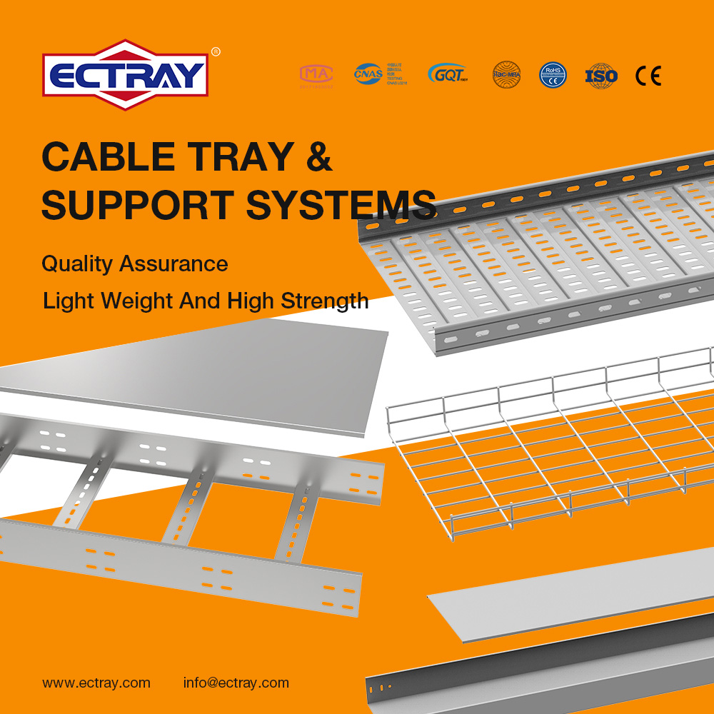
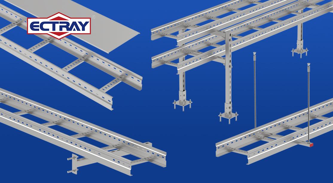
A perforated cable tray supports and routes electrical, control and communication cables using a formed base with openings. Together with fittings, connections and structural supports, it creates an accessible cable pathway through buildings, industrial facilities and infrastructure projects.
Selecting the right system requires more than choosing a width or material thickness. Bottom design, usable space, cable weight, support span and environmental exposure all influence the final specification.
ECTRAY offers perforated cable tray configurations both without bottom stiffening and with stamped bottom reinforcement. Each configuration should be evaluated against the actual cable arrangement and installation conditions.
This guide explains the differences between these designs, outlines available dimensions and materials, and provides a practical selection process for engineers, contractors and procurement teams.
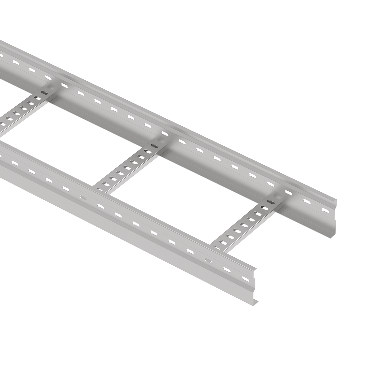
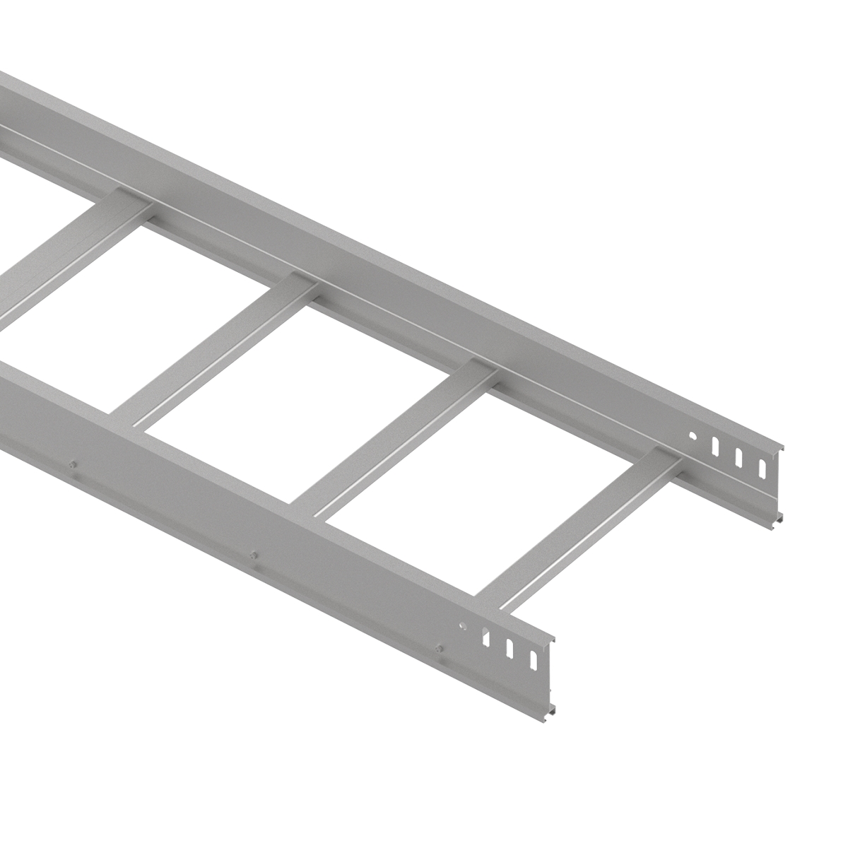
A perforated cable tray is a cable support product with a formed base, sidewalls and openings in the base or sidewalls. Unlike cable ladder, it provides base support between the openings rather than supporting cables on spaced rungs.
The complete system includes the straight sections, fittings, connections and supports required for the cable route.
The tray base supports cables, while the sidewalls and formed edges contribute to the section’s structural behavior. Splice plates connect adjacent sections, and brackets or hangers transfer the load into the supporting structure.
Bends, risers, tees, crosses and reducers accommodate changes in direction, elevation and width. Covers, dividers and bonding components may be included where required.
These components should be selected together. Compatible dimensions, connections, materials and finishes help create a coordinated assembly and reduce missing items during installation.
Perforations provide openings for ventilation and drainage. Depending on the system design, they can also accommodate compatible cable restraints or fixing accessories.
Their effectiveness depends on hole geometry, cable arrangement, mounting orientation and whether covers are installed. Openings alone do not establish cable ampacity, environmental protection or outdoor suitability.
Perforations also affect the remaining material and its load paths. Hole size and spacing therefore need to be considered alongside structural requirements.
Bonding connections should use approved connection details rather than arbitrary holes in the tray.
Perforated cable tray can be considered for power distribution, factory equipment routes, commercial buildings, transport facilities and selected solar installations.
It can accommodate straight runs, branches and elevation changes while maintaining access for cable inspection and modification.
Suitability depends on the cables, load, environment and applicable installation requirements. It should not be classified as suitable only for light loads, nor assumed to support heavy loads without corresponding performance data.
For the products discussed here, the main distinction is whether the perforated base includes additional stamped stiffening.
Material and surface finish are separate selection decisions.
This construction has a perforated base without additional stamped bottom reinforcement. The section still incorporates formed sidewalls and any specified edge details.
ECTRAY’s available material thickness range for this construction is 0.6–2.0 mm.
Its working-load performance depends on thickness, width, sidewall geometry, perforation layout, connections and supports. The absence of stamped bottom ribs does not automatically define a low-load product.
It should be evaluated using data for the proposed configuration and support span.
This design incorporates formed ribs or contours into the perforated base. The shaped profile is intended to improve base stiffness and local resistance to deformation.
ECTRAY’s available material thickness range for this construction is 0.6–1.5 mm.
The reinforcement’s dimensions, direction and spacing influence its effect. Local bottom stiffening does not automatically establish a larger permitted support span or a fixed increase in overall load capacity.
Any performance comparison should use equivalent material, loading and support conditions.
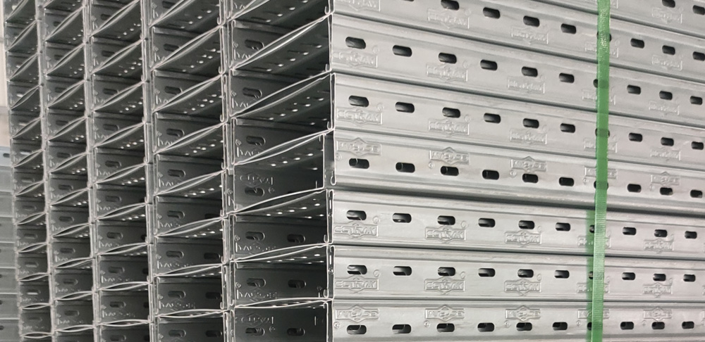
| Selection Item | Without Bottom Stiffening | With Stamped Bottom Reinforcement |
|---|---|---|
| Base construction | Perforated base without additional stamped ribs | Perforated base with formed stiffening contours |
| Available thickness | 0.6–2.0 mm | 0.6–1.5 mm |
| Geometry to review | Base, sidewalls, edges and perforations | Base reinforcement plus the complete section |
| Working load | Verify for the selected configuration | Verify for the selected configuration |
| Support span | Confirm against relevant load data | Confirm against relevant load data |
| Substitution assessment | Compare complete system performance | Compare complete system performance |
Choose between these configurations using project requirements and supporting data. Avoid assuming that one design is always lighter, cheaper or capable of replacing a thicker product.
Tray dimensions affect cable arrangement, available installation space and structural configuration.
The following dimensions describe ECTRAY’s product range. Confirm the available combinations of width, height, thickness and bottom design before ordering.
| Width — mm | Approximate Width — in |
|---|---|
| 100 | 3.94 |
| 150 | 5.91 |
| 200 | 7.87 |
| 300 | 11.81 |
| 400 | 15.75 |
| 500 | 19.69 |
| 600 | 23.62 |
| 700 | 27.56 |
| 800 | 31.50 |
Select width from the actual cable arrangement, required separation and planned additions. A wider tray provides more routing space, but its structural performance still needs verification.
| Sidewall Height — mm | Approximate Height — in |
|---|---|
| 50 | 1.97 |
| 100 | 3.94 |
| 150 | 5.91 |
| 200 | 7.87 |
Sidewall height is not necessarily the usable loading depth. Folded edges, covers, dividers and cable installation requirements may affect the available space.
A deeper tray does not automatically permit additional cable layers.
| Length — mm | Length — m | Approximate Length — ft |
|---|---|---|
| 2000 | 2.0 | 6.56 |
| 2500 | 2.5 | 8.20 |
| 3000 | 3.0 | 9.84 |
Converted values are rounded; the specified metric dimensions govern.
Section length and support span are different. A 3000 mm section may require intermediate supports according to its load data and installation arrangement.
Usable width is the clear space available for the intended cable arrangement. Overall width describes the tray’s external footprint.
Folded edges, connection details and dividers can affect usable space. Check the product drawing to determine what the nominal width represents.
Use internal dimensions for cable arrangement and overall dimensions for coordination with walls, equipment and neighboring services.
Start with cable quantities, outside diameters, weight and minimum bend radii. Identify separation requirements and any planned expansion.
Apply the relevant cable arrangement and fill rules rather than one universal fill percentage. Cable diameter, cable cross-sectional area and tray area are different measurements and should not be used interchangeably.
Fittings must also accommodate the required cable bending space.
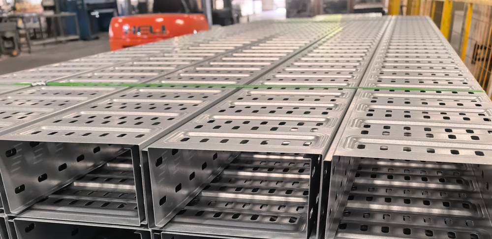
Material thickness affects performance, weight and handling, but it should always be considered with the product geometry.
| Bottom Design | Available Material Thickness |
|---|---|
| Without stamped bottom stiffening | 0.6–2.0 mm |
| With stamped bottom reinforcement | 0.6–1.5 mm |
Specify whether the stated thickness is the base metal thickness and identify the applicable tolerance.
These ranges do not mean every thickness is available in every width, height, material or finish.
Two trays with the same sheet thickness can behave differently because their sidewalls, folded edges, perforations and reinforcement profiles differ.
Connection design and support conditions also affect the complete assembly. Increasing thickness does not resolve every potential weakness in a joint, bracket or local base region.
A useful technical comparison therefore combines dimensions and material specifications with working-load and deflection evidence.
Confirm the cable load and proposed support layout, then review configurations with suitable documented performance.
Check whether the load data applies to the actual width, height, material, thickness and bottom profile being offered.
Do not select a thinner reinforced tray as a substitute solely from a local buckling comparison. Equivalent performance needs verification under the intended installation conditions.
Steel and stainless steel describe base materials. GI, HDG, ZM and powder coating identify coating or finishing options.
A complete specification should distinguish the substrate, material grade and surface protection.
ZM refers to zinc-aluminum-magnesium coated steel.
Its selection should include the coating designation or coating mass, fabrication details and exposure conditions. Cut edges, formed areas and compatible fasteners should be reviewed as part of the assembly.
Corrosion test results can support evaluation, but salt spray hours should not be converted directly into a fixed outdoor service life.
GI is steel galvanized before fabrication. It can be considered for indoor and controlled environments, subject to the actual exposure.
Moisture, condensation and pollutants remain relevant indoors. Cut edges and site modifications should be assessed against the coating specification and any required treatment procedures.
Post-fabrication hot-dip galvanizing applies zinc protection to fabricated components.
For specified outdoor or industrial applications, confirm coating requirements, inspection criteria and repair procedures. Fittings, fasteners and supports should have compatible protection.
The finish should be selected for the exposure rather than described as universally suitable for every outdoor environment.
Stainless steel options may suit projects requiring corrosion-resistant construction.
Grade selection depends on moisture, chlorides, chemical type, concentration, temperature and maintenance. Grade 316 may be evaluated for certain chloride-exposed conditions, but it is not universally resistant to all coastal or chemical environments.
Compatible fasteners and appropriate fabrication practices also matter.
Powder coating provides a specified color and surface finish over a prepared substrate.
Performance depends on the substrate, pretreatment, coating system, exposure and damage repair. Specify these details alongside color requirements.
The presence of powder coating alone does not establish outdoor or chemical resistance.
| Environment | Options to Evaluate | Main Checks |
|---|---|---|
| Indoor, controlled | GI or specified powder-coated steel | Humidity, condensation and coating requirements |
| Industrial | HDG, ZM or suitable stainless steel | Pollutants, moisture and cleaning conditions |
| Outdoor | HDG, ZM or suitable stainless steel | Exposure, drainage and compatible hardware |
| Coastal or chemical | Project-specific material and coating selection | Actual salt or chemical conditions and maintenance |
Load capacity is meaningful only when its configuration and support conditions are defined.
Use cable manufacturer data to calculate:
Cable load per meter = sum of each cable quantity × its weight per meter
For example:
| Cable Group | Quantity | Weight per Cable | Total |
|---|---|---|---|
| Power cable A | 8 | 1.5 kg/m | 12.0 kg/m |
| Power cable B | 6 | 0.8 kg/m | 4.8 kg/m |
| Control cable | 10 | 0.2 kg/m | 2.0 kg/m |
| Total cable weight | 18.8 kg/m |
This is an illustrative cable-load calculation, not an ECTRAY product rating.
Account for planned cable additions, covers, accessories, tray self-weight and other applicable loads on the appropriate design basis.
Compare the required load with the manufacturer’s data for the proposed span and configuration.
Confirm whether the published value represents allowable additional payload or includes tray self-weight. Keep the comparison consistent.
A load value without an associated support span is incomplete. Likewise, a support spacing used on one product should not be transferred automatically to another.
Review deflection requirements alongside strength and stability.
The assessment should account for splice position, connection design, concentrated loads, support layout and any relevant movement conditions.
Brackets, hangers and anchors require their own capacity checks. Adequate tray capacity does not establish the capacity of the supporting assembly.
Required service load is what the installation needs to carry. Allowable working load is the permitted load under the stated conditions and assessment criteria.
Destructive load is associated with failure during a particular test. It is not directly interchangeable with allowable working load.
A linear buckling factor is another distinct result and should not be presented as kg/m capacity.
A complete route needs fittings and supports compatible with the selected straight sections.
| Component | Purpose | Selection Check |
|---|---|---|
| Bends and risers | Change direction or elevation | Cable bend radius and support arrangement |
| Tees and crosses | Create branches | Branch dimensions and cable distribution |
| Reducers | Transition between widths | Geometry and available cable space |
| Splice plates | Connect adjacent sections | Profile, fasteners and connection requirements |
| Covers and clamps | Provide covered sections | Fixing, access and exposure |
| Dividers | Separate cable groups | Required segregation and usable space |
| Brackets and hangers | Support the route | Load, span, substrate and anchorage |
| Bonding components | Provide continuity where required | Approved electrical connection details |
Select fitting geometry to preserve cable support and minimum bend radius.
Branch and elevation changes may need specific support positions. Confirm these details against the system instructions rather than applying straight-run spacing everywhere.
Reducers accommodate changes in route width. Splice plates connect compatible sections using the specified fastening arrangement.
Mechanical connection and electrical continuity requirements should both be checked. A bolted joint should not automatically be assumed to satisfy every bonding requirement.
Covers may be specified where additional enclosure is needed. Assess their effect on access, thermal conditions and, outdoors, wind loading.
A cover does not automatically provide an ingress protection rating.
Dividers help define cable compartments, but their suitability depends on the actual segregation requirements.
Specify support type, material, fixing substrate and anchorage together.
Bonding parts should match the electrical design and system instructions. Use compatible components, particularly where coatings, movement joints or dissimilar materials affect the connection.
Industrial routes may serve distribution equipment, motors and control systems across multiple operating areas.
Selection priorities include cable weight, equipment branches, physical exposure and maintenance access. Different areas within one facility may require different finishes or routing products.
Commercial routes often share limited service space with ventilation, plumbing and other electrical systems.
Tray dimensions, access, cable separation and coordination are important. Confirm that the proposed wiring method is permitted for each cable group, especially systems with additional project requirements.
Airports, railways, bridges and tunnels can involve restricted access, structural movement and demanding environmental exposure.
Review fixing details, transitions, support loads and maintenance arrangements. Material selection should reflect the actual route location.
Rooftop routes require coordination with roof construction, drainage, cable exposure and maintenance access.
Assess roof attachments, applicable wind loads, material compatibility and cable suitability. In energy storage installations, coordinate power and control routing with equipment access requirements.
Cable trays support cables. Personnel walkways need a separate design and should not be treated as part of the tray’s load rating.
List cable type, quantity, outside diameter, weight per meter and bend radius.
Identify separation requirements and define future additions in terms of both space and weight.
Select usable width and depth from the cable arrangement.
Compare configurations without bottom stiffening and with stamped reinforcement using the structural requirements and available evidence.
Check the selected product’s load/span basis, deflection criteria and connection conditions.
Clearly identify any requirement needing additional engineering review or testing.
Describe actual moisture, salt, chemicals, temperature and cleaning conditions.
Specify compatible fittings, fasteners and supports along with the tray finish.
Mark turns, branches, elevation changes, equipment entries and support positions.
Include covers, dividers, connections, movement fittings and bonding parts where required.
Confirm drawings, performance documents, product identification and inspection requirements.
Agree quantities, packaging, delivery destination and schedule with the supplier. Custom configurations and document requirements should be established before production.
Coordinate routes with other services and provide space for cable laying, cover removal and inspection.
Check equipment transitions and penetrations before installation.
Follow the approved support arrangement and system instructions.
Use compatible splice hardware and specified fastening procedures. Provide movement provisions where the route and structural design require them.
Maintain the cable manufacturer’s bending requirements through fittings and drops.
Treat field cuts and exposed edges using approved methods, including coating repair where required.
Apply the project’s bonding and grounding requirements. Do not assume every metal tray is suitable for use as a grounding conductor.
Inspect supports, joints, cable arrangement, edges, coatings and required electrical connections before acceptance.
IEC 61537 addresses cable tray and cable ladder systems. Project specifications should identify the applicable edition and required evidence.
Local electrical requirements govern cable suitability and installation. Where another product standard is specified, confirm its exact designation and scope.
Cable trunking is a separate product category and should not be treated as interchangeable with perforated cable tray.
Request documents relevant to the offered configuration:
An ISO 9001 certificate addresses the quality management system. Product certificates and test reports should be checked separately for model coverage and test conditions.
ECTRAY manufactures perforated cable trays with different dimensions, thicknesses, bottom profiles and surface finishes.
To prepare a useful quotation, provide:
| Information | Details |
|---|---|
| BOQ and route drawings | Quantities, route lengths, fittings and equipment entries |
| Cable schedule | Cable quantities, diameters and weight |
| Tray configuration | Width, height, thickness and bottom design |
| Support conditions | Proposed span, supports and connection requirements |
| Environment | Indoor, outdoor, coastal or chemical exposure |
| Material and finish | Grade and coating requirements |
| Documentation | Required drawings, reports and certificates |
| Delivery | Destination and project schedule |
Explore ECTRAY’s perforated cable tray range and send your project requirements for review.
Share your BOQ, cable load and installation conditions with ECTRAY to discuss a suitable configuration and request a quotation.
It supports and routes suitable power, control and communication cables. Straight sections, fittings, connections and structural supports form the complete system.
The standard design discussed here has no additional stamped bottom stiffening. The reinforced design includes formed contours intended to improve base stiffness. Overall performance depends on the complete configuration.
ECTRAY’s range includes widths from 100–800 mm, heights of 50, 100, 150 and 200 mm, and lengths of 2000, 2500 and 3000 mm. Thickness ranges differ by bottom design. Confirm specific combinations before ordering.
Use working-load and installation data for the selected configuration, together with cable load, connection details and structural conditions. Product length alone does not determine spacing.
Yes, where the complete system and cables suit the exposure. Review corrosion protection, drainage, fixing, structural loads and cable requirements.
No. Cover requirements depend on the environment, exposure and project specification. Consider access, thermal conditions and fixing requirements when selecting one.
Only after the proposed configurations are assessed against the same performance requirements. A local simulation result or thickness comparison alone does not establish equivalence.
Perforated tray supports cables on a formed base with openings. Cable ladder supports cables on spaced rungs. Selection depends on cable requirements, load, access and installation conditions.
Provide the BOQ, cable schedule, dimensions, bottom design, support conditions, material, finish, environment and documentation requirements. Identify undecided details so quotation assumptions can be reviewed.