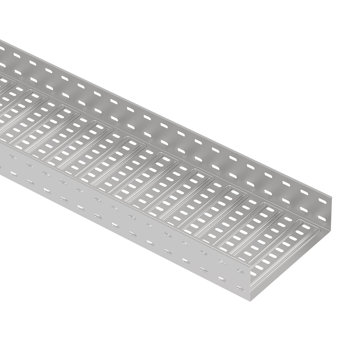
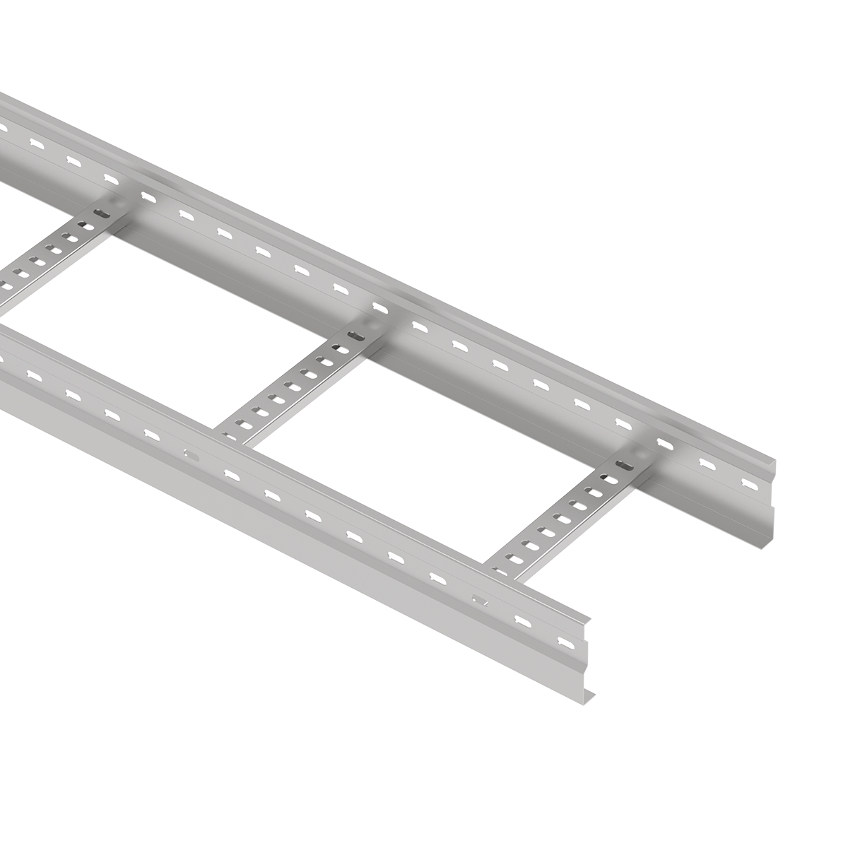
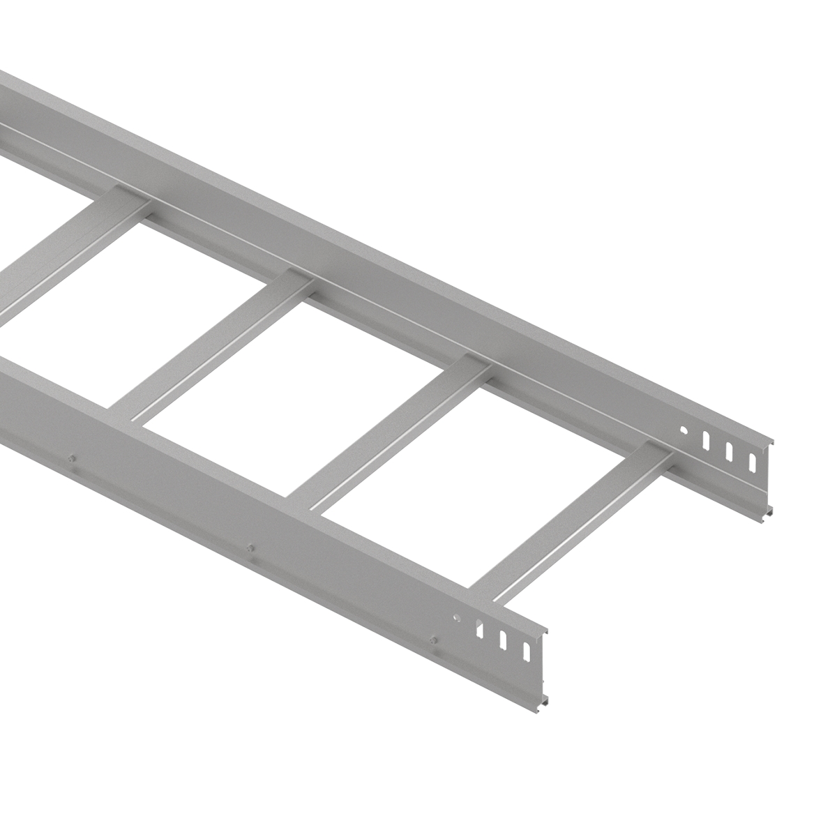
A cable ladder system is more than a series of straight sections. Its performance also depends on the fittings that guide cables through changes in direction, the brackets that support the route, and the accessories that connect and organize the installation.
Selecting the right cable ladder accessories begins with understanding what each component does and how it interacts with the rest of the system. A bracket must suit both the ladder and the supporting structure. A bend must accommodate the cables passing through it. A splice plate must match the side rail and connection details.
This guide explains the functions and selection considerations of cable ladder bends, tees, crosses, support brackets, splice plates, dividers, bonding jumpers and cover clamps.
Cable ladder accessories and fittings complete the cable support system. They allow straight ladder sections to follow the project layout, connect to supporting structures and accommodate cable management requirements.
Although suppliers may classify components differently, distinguishing routing fittings from installation accessories makes specification and procurement easier.
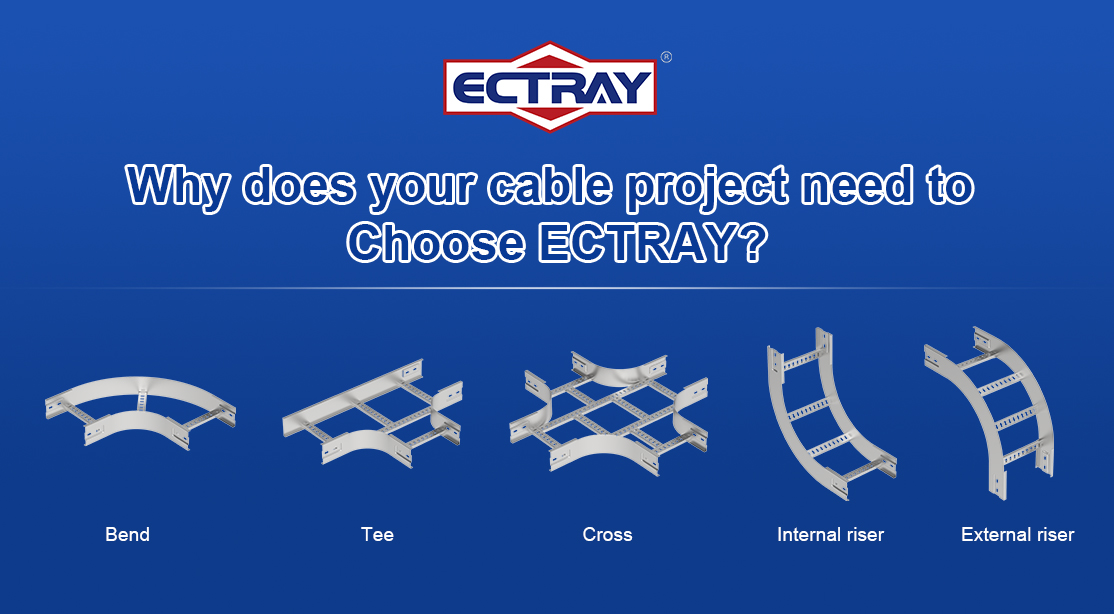
Fittings change the direction or branching arrangement of the cable ladder route.
Typical examples include:
Their geometry affects the space available for cable routing, particularly at turns and branches.
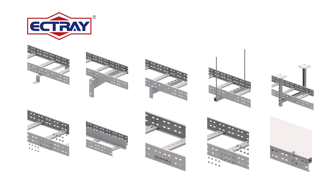
Accessories support, connect, separate or secure components within the system.
ECTRAY’s existing accessory range includes underfloor stands, wall brackets, straight brackets, straight ceiling brackets, splice plates, dividers, bonding jumpers and cover clamps.
| Component | Main Function | Main Selection Consideration |
|---|---|---|
| Bend | Changes route direction | Angle, radius and ladder dimensions |
| Tee | Creates a three-way route connection | Branch dimensions and cable routing space |
| Cross | Creates a four-way route connection | Route layout and support arrangement |
| Underfloor stand | Supports a ladder beneath a floor | Installation height and available clearance |
| Wall bracket | Supports a ladder from a wall | Projection, load and fixing conditions |
| Straight bracket | Provides support or attachment according to its design | Bracket geometry and connection details |
| Straight ceiling bracket | Supports a ladder from an overhead structure | Suspension arrangement and fixing conditions |
| Splice plate | Connects adjacent ladder sections | Side rail profile, hole pattern and hardware |
| Divider | Separates cable routing areas | Height, position and fixing method |
| Bonding jumper | Provides an electrical connection at specified locations | Electrical design and connection requirements |
| Cover clamp | Secures a compatible cover | Cover profile and clamp engagement |
Routing fittings should be selected from the cable layout rather than added after the straight sections have been ordered. Turns and branches often determine whether the proposed route provides enough room for the cables.
A horizontal bend changes the direction of a cable ladder within the same horizontal plane. It may be used to follow a corridor, turn around a structural obstruction or redirect a route toward equipment.
The main selection details are ladder width, side rail height, bend angle and radius.
Bend radius requires particular attention. The fitting must provide a cable path that accommodates the cable manufacturer’s minimum bending radius, including any different requirements for installation and final positioning.
A fitting that fits the building layout may still be too tight for the intended cables. Check the cable requirements before finalizing the fitting dimensions.
Vertical bends allow the cable ladder route to change elevation. They are used where the route rises, drops or transitions between horizontal and vertical sections.
Inside and outside vertical bends have different geometries. Because terminology and drawing conventions can vary, confirm the required orientation using a layout or product drawing.
Selection should consider:
The bend guides the route, while cable restraint must be addressed separately where required by the design.
A tee provides a three-way connection, allowing cables to branch from a main route.
A common application is a main distribution route feeding a secondary area or equipment group. The tee should provide sufficient space for cables to continue along the main route or turn into the branch without crowding.
Specify the width of each connection and show the intended cable directions on the layout. This is especially useful when the branch arrangement is difficult to describe in a written BOQ.
A tee also needs an appropriate support arrangement. Its branching geometry should be reviewed separately from the support spacing used for straight ladder sections.
A cross provides a four-way route connection. It can be useful where several cable routes meet within a distribution area.
The additional routing options require careful planning. Cable paths may overlap or compete for space at the intersection, making installation and later cable additions more difficult.
Before selecting a cross, review how cables will pass through the intersection, whether separation is required and how the fitting will be supported.
| Fitting | Typical Purpose | Information to Specify |
|---|---|---|
| Horizontal bend | Turns the route on the same level | Width, rail height, angle and radius |
| Vertical bend | Changes route elevation | Dimensions, orientation, angle and radius |
| Tee | Adds a branch to a main route | Connection widths, orientation and routing requirements |
| Cross | Connects four route directions | Connection widths, layout and support requirements |
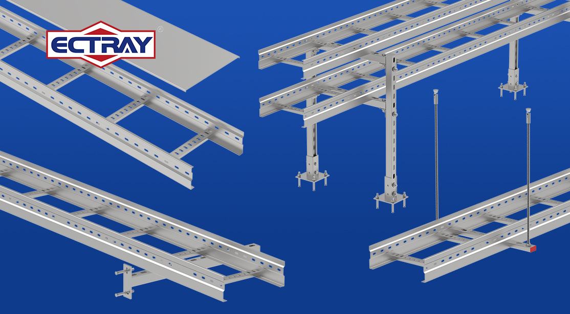
Support accessories transfer the load of the ladder and cables to the building structure. Their selection must account for the ladder, bracket, fixings and installation substrate together.
Underfloor stands support cable ladder sections beneath a floor, including installations with accessible underfloor service spaces.
The stand height should provide the required routing level while allowing room for cables, fittings and access. Check the clearance above the ladder, particularly where cables need to enter, leave or turn within the route.
The installation base also matters. Confirm how the stand attaches to the substrate and whether the proposed fixing arrangement suits the project loads.
Wall brackets support cable ladders along walls or other suitable vertical structures.
Bracket projection should accommodate the ladder width and its intended position. It must also leave enough space for cable installation, inspection and nearby services.
A bracket’s capacity cannot be assessed independently of its fixings and the wall. The bracket, anchors and substrate must all suit the loading and installation conditions.
Straight brackets provide support or attachment according to their particular geometry.
The name alone does not define the installation arrangement. Selection should therefore use the product drawing to confirm the bracket’s dimensions, hole pattern, orientation and mating components.
For procurement, include a drawing reference or product code rather than relying only on the description “straight bracket.”
Straight ceiling brackets are used in overhead support arrangements.
Their selection depends on the overhead structure, installation height, connection method and any associated suspension components. Check that the arrangement provides access for cable installation and future maintenance.
Where several cable ladder levels share a support assembly, assess the combined load and the space between levels.
| Support Accessory | Key Checks |
|---|---|
| Underfloor stand | Height, base fixing, clearance and cable access |
| Wall bracket | Projection, load, anchors and wall condition |
| Straight bracket | Drawing, orientation, hole pattern and mating components |
| Straight ceiling bracket | Overhead fixing, suspension arrangement and installation height |
Splice plates connect adjacent ladder sections and compatible fittings. They form part of the mechanical connection and should be selected for the specific ladder series.
Nominal ladder width is not enough to establish compatibility.
Check the side rail height and profile, connection hole pattern, splice plate dimensions and specified hardware. Different product series may use different connection details even when their nominal dimensions are similar.
Material and finish should also be compatible with the connected ladder sections and the installation environment.
A splice connection includes the plate and its specified bolts, nuts, washers or other hardware.
Use the manufacturer’s assembly instructions and tightening requirements. Check alignment and ensure that the installed hardware does not create an unsuitable contact point for cables.
An ordinary splice plate should not be assumed to accommodate thermal movement. Where expansion provisions are required, the connection must be designed and specified for that purpose.
A divider creates separate routing areas within a cable ladder. It can help organize different cable groups and make the route easier to identify and maintain.
Divider position should follow the cable arrangement. Consider how much width each group requires and how the separation will continue through bends, branches and other transitions.
A divider can consume usable space, so include it when assessing the available cable routing area.
The divider should match the ladder structure and the intended cable arrangement.
Confirm its height, fixing method, connection hardware and treatment at section ends. The installed arrangement should avoid edges or projections that could damage cables.
Physical separation does not automatically establish electromagnetic shielding or compliance with every cable segregation requirement. Those requirements must be assessed through the project design.
A bonding jumper provides an electrical connection between specified metallic components. Its use forms part of the system’s bonding design.
Whether a connection needs a bonding jumper depends on the system, joint construction and applicable electrical requirements.
A mechanically secure joint should not automatically be assumed to provide the required electrical continuity. Equally, separate jumpers should not be specified at every joint without checking the approved system details.
Review the manufacturer’s connection information and the project’s bonding requirements.
Jumper selection includes conductor size, length, terminal compatibility and the attachment method.
The complete connection must suit the electrical requirements and environmental conditions. Contact surfaces, finishes and attachment hardware should be addressed in the installation instructions.
Bonding jumpers support the bonding arrangement; their presence alone does not establish that the cable ladder is approved for use as a protective conductor.
Cover clamps secure compatible covers to the cable ladder. Their suitability depends on the relationship between the clamp, cover profile and ladder structure.
Check how the clamp engages with the cover and side rail. A clamp that appears similar may not provide the intended engagement on another product series.
Specify the ladder series, cover type and clamp reference together to reduce procurement errors.
Cover fixing should allow secure installation while providing access for inspection and maintenance.
Outdoor installations require particular attention to the cover fixing arrangement and project wind loads. The number and placement of clamps should follow the approved design and product instructions.
Cover clamps secure covers; the broader protective performance depends on the complete cover arrangement.
Selection is most effective when the route, cables and supporting structure are reviewed together.
Identify turns, elevation changes, branches and intersections on the drawing. Mark support locations and areas where access is restricted.
This establishes the required fittings and reveals potential conflicts before procurement.
Record the ladder series, width, side rail height, profile and connection details.
For bends, tees and crosses, include the relevant orientation and radius. For brackets and connection accessories, use product codes or drawing references wherever possible.
Consider the ladder weight, cable load and design allowance for future additions.
Review fittings and their supports separately from straight sections. A straight-section load rating should not be applied automatically to a bend, tee, cross or bracket assembly.
Accessories should suit the ladder material and operating environment.
Depending on confirmed availability, project specifications may involve GI, HDG, ZM, stainless steel or other materials and finishes. Review coating specifications, moisture exposure, chemicals and any contact between dissimilar metals.
A material description alone is not a complete corrosion specification.
Include the smaller components needed to finish the installation: connection hardware, divider fixings, bonding terminals and cover clamps.
A complete BOQ helps avoid ordering a major component without the hardware needed to install it.
A clear accessory schedule improves quotation accuracy and makes technical review easier.
| BOQ Item | Recommended Information |
|---|---|
| Bends | Type, width, rail height, angle, radius, finish and quantity |
| Tees and crosses | Connection widths, orientation, finish and drawing reference |
| Underfloor stands | Height, dimensions, fixing details and quantity |
| Wall brackets | Projection, dimensions, load requirements and quantity |
| Straight brackets | Product code or drawing, dimensions and quantity |
| Straight ceiling brackets | Drawing reference, installation arrangement and quantity |
| Splice plates | Ladder series, rail details, hardware and quantity |
| Dividers | Height, length, position, fixing method and quantity |
| Bonding jumpers | Conductor specification, terminals, length and quantity |
| Cover clamps | Ladder and cover references, clamp type and quantity |
State whether quantities refer to individual pieces, pairs or complete kits. For example, a splice plate quantity should make clear whether associated hardware is included.
Descriptions such as “wall bracket” or “splice plate” do not establish compatibility. Product drawings and connection details provide the information needed for a reliable selection.
A route may appear adequate along its straight sections but become crowded at a bend or branch. Review cable paths through fittings before finalizing the layout.
Mechanical connection, electrical continuity and thermal movement are separate design considerations. Check each requirement rather than assuming one connection detail addresses all three.
Missing fasteners, terminals or clamps can delay installation even when the main ladder sections are available. Review each assembly as a complete set of components.
ECTRAY supplies cable ladder bends, tees and crosses alongside underfloor stands, wall brackets, straight brackets, straight ceiling brackets, splice plates, dividers, bonding jumpers and cover clamps.
Selecting these components as a coordinated system helps align the route geometry, connections and support arrangements with the project requirements.
For information about the ladder itself, explore ECTRAY Steel Cable Ladder.
Planning a new cable ladder installation or preparing a project BOQ?
Send ECTRAY your layout, ladder dimensions, material requirements and accessory schedule. Include cable bending requirements and installation drawings where available so the proposed components can be reviewed against the intended application.
Contact ECTRAY for cable ladder accessory selection and quotation support.
The required accessories depend on the route and installation method. Typical items include support brackets, splice plates and connection hardware. Dividers, bonding jumpers and cover clamps are added according to the cable arrangement and project requirements.
Bends, tees and crosses are selected where the route changes direction or branches.
Check the ladder dimensions, turn direction, fitting angle and available space. Confirm that the cable path through the bend accommodates the cable manufacturer’s minimum bending radius.
Use a drawing to identify vertical bend orientation.
A tee provides three route connections, commonly allowing a branch from a main route. A cross provides four route connections.
Selection depends on the layout, cable paths and support arrangement at the junction.
Compatibility must be confirmed. Matching nominal dimensions does not guarantee matching side rail profiles, holes, cover details or connection performance.
Check the drawings and obtain confirmation before mixing product series.
Consider the ladder width, required projection or installation height, load and fixing conditions.
Assess the complete support arrangement, including anchors and the building substrate.
The requirement depends on the joint construction, approved system information and applicable electrical design requirements.
Check whether the specified connection provides the required continuity and where separate jumpers are required.
A divider can provide physical separation and improve cable organization. Its presence alone does not demonstrate sufficient electromagnetic shielding.
Cable separation and interference control should follow the project’s electrical design.
The quantity and placement depend on the ladder and cover system, installation conditions and approved fixing requirements.
For outdoor installations, include the relevant wind loading conditions when confirming the fixing arrangement.