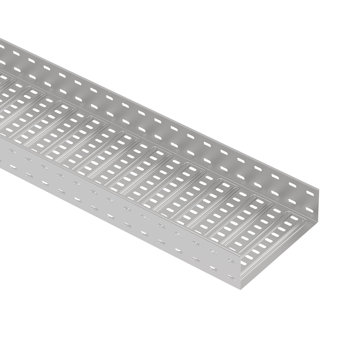
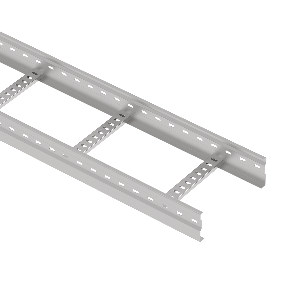
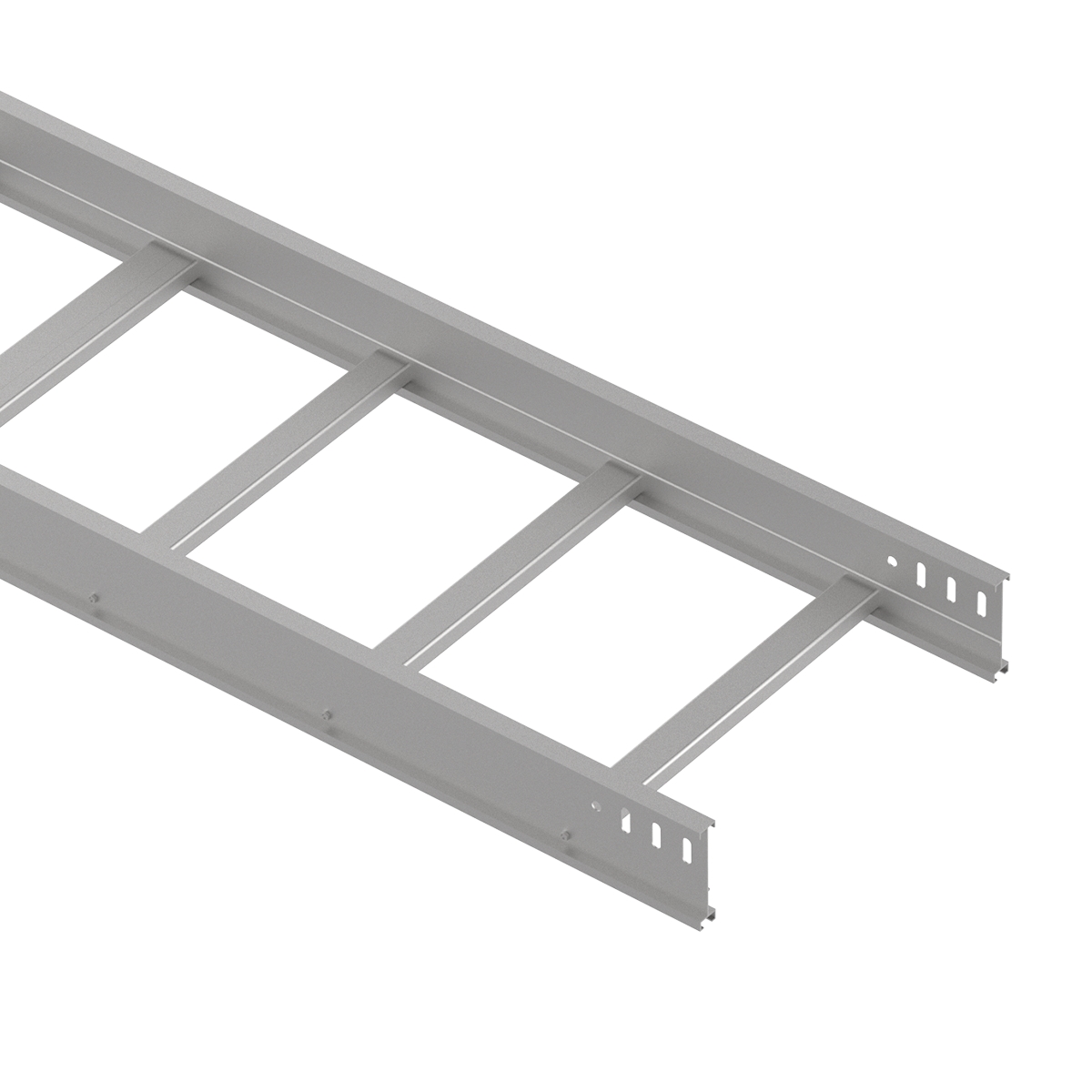
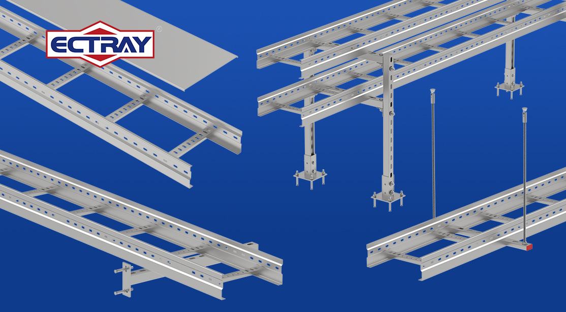
Choosing the right cable ladder sizes starts with three dimensions: width, side rail height and straight section length. These determine the space available for cable routing and help coordinate the ladder with supports, fittings and the installation route.
Dimensions are only part of the specification. Cable weight, laying arrangement, support span, material and structural design must also be checked. Two ladders with the same dimensions can have different load ratings.
This guide covers ECTRAY cable ladder widths from 200 to 1000 mm, side rail heights of 100, 150 and 200 mm, and section lengths of 2000, 3000 and 6000 mm. It includes millimeter-to-inch conversions, practical selection steps and an explanation of NEMA requirements.

Before comparing cable ladder sizes, confirm what each dimension represents on the manufacturer's drawing. A specification written as W × H × L should identify the width reference, side rail height and straight section length.
Usable width is the clear horizontal space available for the specified cable arrangement. Overall width includes the side rails and any outward projections shown on the product drawing.
Use the clear width when checking cable layout. Use the overall dimensions when checking clearance around walls, equipment and adjacent services, and when coordinating supports.
A published nominal width may refer to different measurement points across product ranges. Confirm the drawing before ordering or comparing manufacturers.
Side rail height is the vertical dimension of the rail. Usable loading depth is the space available above the cable-bearing surface of the rungs, within the relevant containment height.
Rung profiles, rail returns and hardware can reduce that space. Using the full side rail height as available loading depth can therefore overestimate the room for cables.
Check the cross-section drawing together with the permitted cable arrangement. Additional height does not automatically permit additional cable layers.
Straight section length is the manufactured length of an individual ladder section. Support span is the distance between adjacent supports.
For this ECTRAY size range, section lengths are 2000, 3000 and 6000 mm. Selecting one of these lengths does not establish its allowable support span.
The support layout must follow the selected product's load data and installation instructions, including requirements for joints, fittings and changes in direction.
The following tables show the dimensional range covered in this guide. Confirm the available combinations, measurement references and tolerances for the selected product series before ordering.
Conversion: 1 inch = 25.6 mm. Inch values are conversions of the metric dimensions, rounded to two decimal places.
| Width (mm) | Width (inches) |
|---|---|
| 200 | 7.87 |
| 300 | 11.81 |
| 400 | 15.75 |
| 500 | 19.69 |
| 600 | 23.62 |
| 700 | 27.56 |
| 800 | 31.50 |
| 900 | 35.43 |
| 1000 | 39.37 |
Select width from the cable layout and required separation. A narrower ladder can carry heavy cables if its structural rating is suitable, while a wider ladder may be needed for numerous lightweight cables. Width alone does not define a duty or load class.
| Side Rail Height (mm) | Side Rail Height (inches) |
|---|---|
| 100 | 3.94 |
| 150 | 5.91 |
| 200 | 7.87 |
These heights provide options for coordinating loading depth, cable arrangement and site clearance. The working load for each height must be confirmed against the particular ladder design and support span.
| Section Length (mm) | Section Length (inches) |
|---|---|
| 2000 | 78.74 |
| 3000 | 118.11 |
| 6000 | 236.22 |
These lengths correspond to 2 m, 3 m and 6 m. Shorter sections can be easier to move through restricted access points. Longer sections may reduce joints on suitable straight runs, depending on the route and cutting plan.
A metric size should not be substituted for a nominal inch size without checking the drawing. For example, 300 mm equals approximately 11.81 inches, whereas 12 inches equals 304.8 mm.
Cable ladder width should be selected from the cable schedule and arrangement required along each route. Check congested locations as well as typical straight runs.
Collect the cable type, quantity, outside diameter and weight per unit length. Confirm whether the design requires single-layer, grouped, trefoil or another permitted arrangement.
For an approved single-layer layout, the sum of cable diameters provides a starting point. Add the required gaps, edge clearances, space for cleats or separators, and any defined reserve.
For other arrangements, use the applicable sizing method. A simple sum of diameters does not cover every installation.
Separation requirements depend on cable type, circuit arrangement, thermal conditions and project specifications. Power, control and communication circuits may also require separate routes or designated zones.
Future capacity should be defined with the project team. Reserve space may be based on known additional circuits or an agreed allowance, but it must satisfy the applicable fill and arrangement rules.
Check future weight as well as future space. Spare width does not establish spare structural capacity.
For an approved single-layer arrangement, a practical layout calculation is:
Required usable width = cable diameters + specified gaps + edge allowances + reserved space
Select an available size whose confirmed usable width accommodates the result.
For NEC-based projects, check the adopted edition of Article 392, including the relevant cable-fill and arrangement provisions. There is no single 60% fill rule that applies to every cable ladder installation.
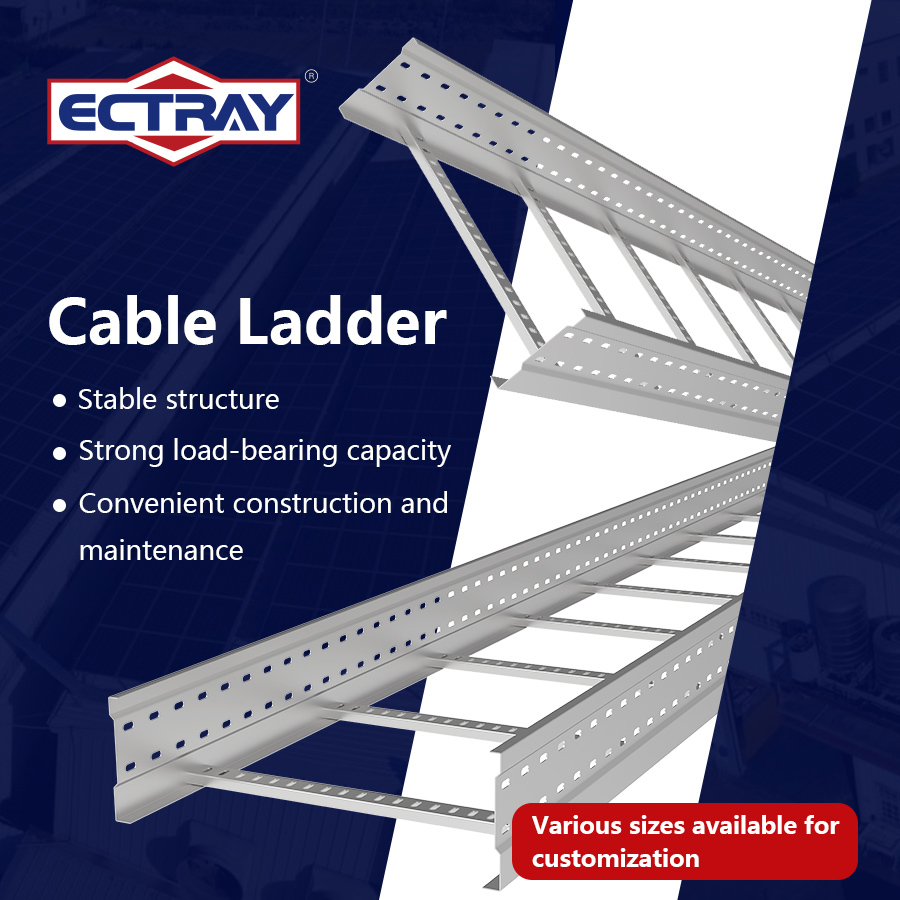
Select side rail height after reviewing the permitted cable arrangement, usable loading depth and available installation space.
A 100 mm (3.94 in) rail may suit a layout with sufficient internal depth and restricted vertical clearance. The 150 mm (5.91 in) and 200 mm (7.87 in) options provide taller rail profiles where the layout or structural design calls for them.
Compare each option using its drawing and load table. Do not assign light-, medium- or heavy-duty ratings solely from these heights.
Check the usable depth against the largest cables, their permitted arrangement, fixing hardware and any covers. Also allow the access required for installation, inspection and maintenance.
Clearance above cables should follow the cable requirements, product design and project specification. A fixed allowance of 10% of cable diameter is not a universal design rule.
Where a single layer is required, choosing taller rails does not remove that requirement.
Structural performance depends on the rail profile, material, thickness, rung construction, connections and support span.
A deeper rail can contribute to bending resistance, but the complete ladder assembly determines the verified rating. Select from the manufacturer's working-load data for the specified configuration.
A destructive test result also needs careful interpretation. The failure load is not the allowable working load; the relevant test method, safety factor and design criteria must be applied.
Choose section length by coordinating the route, supports, joints and installation logistics.
| Section length | Practical considerations |
|---|---|
| 2000 mm / 78.74 in | Easier to maneuver where access or working space is restricted; may require more joints on long runs. |
| 3000 mm / 118.11 in | An intermediate option to evaluate against handling limits, route geometry and support locations. |
| 6000 mm / 236.22 in | May reduce joints on suitable straight runs; requires sufficient delivery, storage and handling space. |
The best length depends on the installation plan. Longer sections do not automatically allow wider support spacing.
Develop the support and joint layout together, using the manufacturer's requirements for the selected ladder system.
Splices should not automatically be placed directly over supports. Their permitted positions depend on the connection design and tested configuration. Fittings and expansion joints can have additional support requirements.
Check access through doors, shafts, lifting routes and crowded service areas before finalizing section length.
Review vehicle capacity, lifting arrangements, storage space and the route from delivery to installation.
Where site cutting is necessary, follow the product instructions for cutting, edge finishing, coating repair and replacement connection holes. Plan cuts and fittings early to reduce waste and avoid poorly positioned joints.
NEMA requirements help specify and evaluate metal cable ladder systems. Dimensional selection, structural performance and installation planning should be checked against the relevant project requirements.
The metal cable tray systems standard previously designated NEMA VE 1-2017 is listed as NEMA BI 50015-2017 (2024), Metal Cable Tray Systems.
It addresses requirements for metal cable trays and associated fittings. Identify the edition required by the project and obtain the relevant product documentation. A dimensional listing alone does not demonstrate compliance.
Traditional NEMA span/load designations such as 8A, 12B and 20C remain widely used in specifications. The number represents the support span in feet, and the letter represents the uniformly distributed working-load category.
| Traditional load designation | Working load (lb/ft) | Working load (approx. kg/m) |
|---|---|---|
| A | 50 | 74.4 |
| B | 75 | 111.6 |
| C | 100 | 148.8 |
For example, 12B describes a 12 ft support span—3657.6 mm (144 in)—with a working load of 75 lb/ft, approximately 111.6 kg/m.
This explains the designation; it does not assign a rating to ECTRAY's dimensional range. Verify the selected model's load/span data and the applicable test basis.
NEMA BI-50016-2024, Cable Tray Installation Guidelines, was formerly designated NEMA VE 2-2018.
Use the applicable installation guidance and manufacturer instructions to coordinate supports, connections and fittings. Check cable fill, permitted arrangement and electrical requirements against the adopted electrical code and project specification.
Project requirements may also include environmental loads, corrosion exposure, seismic conditions or other service conditions requiring additional review.
The following hypothetical example demonstrates a preliminary width calculation. Its spacing and reserve allowances are project assumptions, not universal requirements.
Assume the approved layout calls for:
The cable schedule must separately provide cable weights and confirm the electrical suitability of the assumed arrangement.
Calculate the preliminary usable width:
Required usable width = (8 × 40) + (7 × 10) + 80 = 470 mm (18.50 in)
A nominal 500 mm (19.69 in) ladder is a candidate, provided the drawing confirms at least 470 mm of usable width.
For illustration, the preliminary specification could be:
500 × 150 × 3000 mm (W × H × L)
19.69 × 5.91 × 118.11 in
The 150 mm rail height and 3000 mm section length would still need confirmation against usable depth, clearance, handling and support requirements.
Calculate the cable load from the quantity and weight per unit length. Add defined future cable loads and other applicable loads using the basis stated in the manufacturer's load data.
Then verify:
Release the specification only after these checks are complete. A satisfactory width calculation is one part of the selection.
The range covered here includes widths of 200–1000 mm (7.87–39.37 in), rail heights of 100, 150 and 200 mm (3.94, 5.91 and 7.87 in), and lengths of 2000, 3000 and 6000 mm (78.74, 118.11 and 236.22 in). Confirm available combinations for the selected series.
The dimensions differ. A 300 mm ladder converts to approximately 11.81 inches; 12 inches equals 304.8 mm. Confirm nominal size, actual dimensions and fitting compatibility before substituting one specification for another.
Height alone does not establish the rating. Compare the complete construction and working-load data at the required support span, including material, thickness, rungs and connections.
A 3000 mm (118.11 in) section length does not confirm that span. The selected system must have suitable load data and an installation layout that meets its support and splice requirements.
State W × H × L, identify the width reference, and include material, finish, thickness or product series, rung spacing, required working load, support span and applicable standard. List fittings and accessories separately with compatible dimensions.
Custom dimensions and configurations can be reviewed against the drawings, cable layout and manufacturing requirements. Confirm dimensions, compatible fittings and the necessary structural verification before approving a customized specification.
Selecting cable ladder sizes requires a coordinated check of cable space, structural capacity and installation conditions. Begin with the cable schedule, choose suitable dimensions, and verify the complete system at the proposed support span.
Provide the required width, rail height and section length, together with:
Include route drawings and access constraints where available.
ECTRAY can review cable ladder requirements using your BOQ, cable schedule and project drawings. Providing this information helps coordinate dimensions, materials, supports and accessories before quotation.
Send your BOQ, drawings or project specifications to ECTRAY to discuss the cable ladder sizes required for your installation.