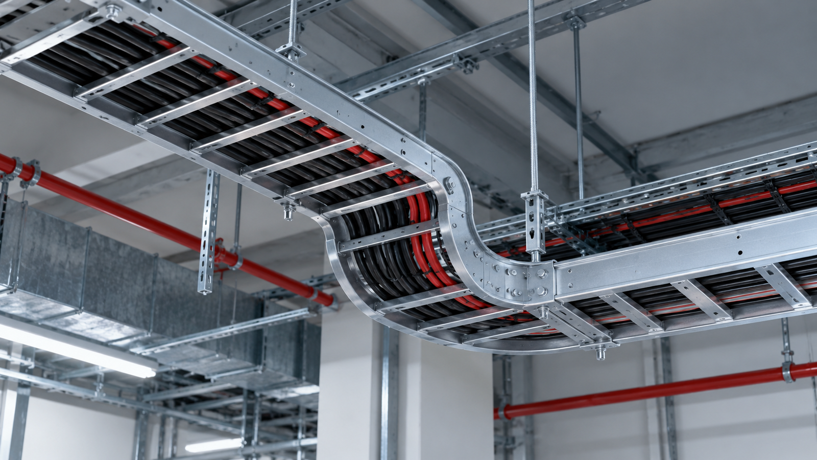
Selecting a perforated cable tray involves more than choosing a width that accommodates the cables. Perforated cable tray load capacity must match the expected cable weight at the proposed support spacing, while the complete system must meet the applicable deflection and connection requirements.
Two trays with the same width and nominal thickness may perform differently because of their sidewall profiles, bottom reinforcement, perforation patterns, materials and installation arrangements. A load value therefore becomes useful only when its supporting conditions are clearly defined.
This guide explains the factors affecting perforated cable tray load capacity, how to estimate cable load demand, and what to verify when selecting support spacing. It also compares bottoms with and without reinforcing ribs and explains how to assess available test information.
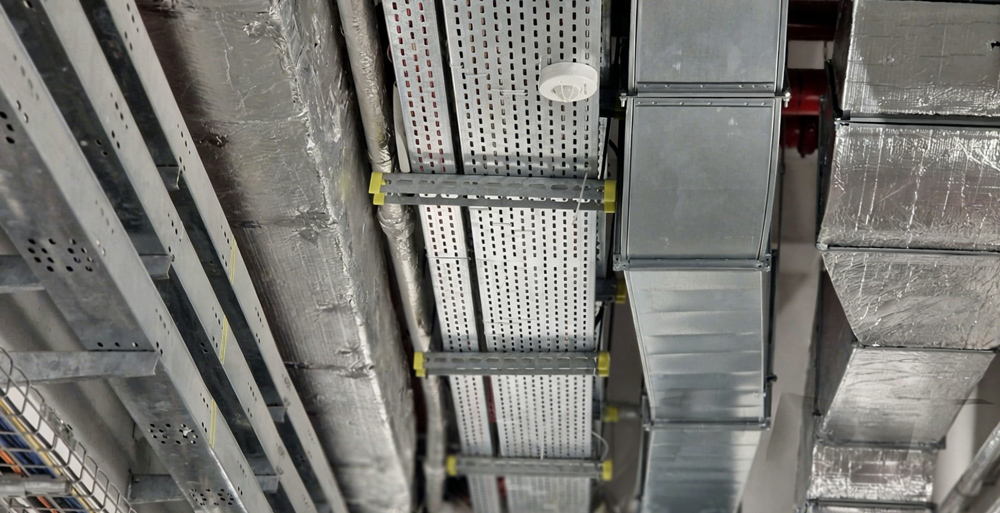
Perforated cable tray load capacity describes the load a specified tray can support under defined conditions. Those conditions include the support span, loading arrangement, connection details and performance criteria.
A statement such as “this tray supports 50 kg/m” is incomplete without identifying the product configuration and the conditions behind that figure.
Support span is the distance between adjacent support points along the tray route.
When reviewing a load rating, confirm:
These details establish whether the information applies to the proposed installation.
Load capacity and fill capacity answer different questions.
Load capacity concerns the weight the tray system can support. Fill capacity concerns the space available for cable installation under the applicable electrical requirements.
A tray can have enough space for additional cables while lacking sufficient structural capacity for their weight. It can also satisfy structural requirements while being unsuitable for the required cable arrangement, separation or heat dissipation.
Both checks are necessary. Available space alone does not establish that more cables can be added.
These terms should be distinguished when reviewing product information.
| Term | Meaning | Relevance to Selection |
|---|---|---|
| Working load | Permitted service load under stated conditions | Used to check suitability for the installation |
| Deflection | Displacement or bending under load | Used to assess service performance |
| Failure load | Load associated with a defined failure condition during testing | Requires interpretation before any working-load claim |
| Fill capacity | Space available for the permitted cable arrangement | Checked separately from structural loading |
A maximum destructive load is not automatically an allowable working load. Any conversion requires the applicable assessment method, acceptance criteria and safety provisions.
Perforated cable tray load capacity depends on the complete structural configuration. No single dimension provides a reliable rating on its own.
Base metal thickness is an important input to structural performance. However, a thickness value must be considered alongside the tray profile, material properties and support arrangement.
When comparing products, distinguish the steel substrate thickness from the finished thickness that includes coatings.
It is also useful to confirm how thickness is measured and what manufacturing tolerance applies. Comparing nominal values without this information can obscure meaningful differences between products.
The longitudinal sidewalls form part of the tray’s structural section. Their height, folded edges and profile influence how the tray resists bending.
A deeper sidewall may contribute to improved performance, but height alone does not establish the allowable load. Material thickness, edge geometry, bottom connection and local stability also require consideration.
For procurement, a section drawing provides more useful information than sidewall height alone.
Tray width determines the available routing space and affects how the bottom carries cable loads.
A wider tray should not automatically be assumed to carry more weight. Its performance depends on the complete section and how cables are distributed across it.
The design should consider whether cables will be evenly arranged or concentrated along one side. Cable bundles and heavy cable groups can create loading conditions that differ from an ideal uniformly distributed load.
Bottom reinforcing ribs change the geometry of the sheet and can improve local stiffness. Perforation size, spacing and position also influence the remaining material and its response to loading.
These features should be assessed together.
The presence of reinforcing ribs does not establish a fixed increase in whole-tray load capacity. The result depends on the rib geometry, sidewalls, material, connections and support conditions.
Base material properties influence mechanical performance. Surface finishes primarily provide protection appropriate to the installation environment.
Specifications such as ZM, GI, HDG and powder coating describe coating or finishing choices; they do not independently define the tray’s load capacity.
For structural comparison, identify the substrate grade and thickness. For durability, assess the environmental exposure and the suitability of the selected material and finish.
The tray section forms only one part of the installed system.
Splice plates, fasteners, brackets, hangers and anchors must transfer loads through the installation. Joint position and connection design may also affect performance.
Product selection should therefore consider the tray and its supporting components together.
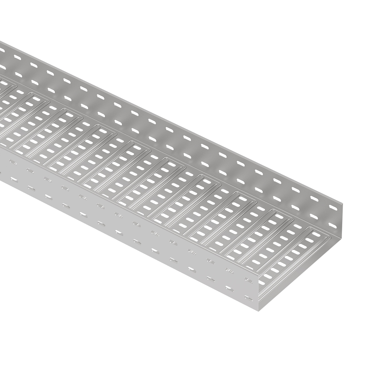
ECTRAY perforated cable trays include designs with bottom reinforcing ribs and designs without bottom reinforcing ribs.
Understanding their structural differences helps define the right questions during selection.
A bottom without reinforcing ribs provides a comparatively simple sheet profile.
Its suitability depends on the complete tray configuration, including actual thickness, sidewall geometry, width, perforation pattern and support spacing.
The absence of bottom ribs does not, by itself, make the product unsuitable for a project. It means its performance must be established for the required loading conditions.
Formed ribs introduce depth into the bottom profile and can improve its resistance to local deformation.
This feature may be useful where bottom stiffness is an important design consideration. However, overall tray performance may still be governed by the sidewalls, joints or other parts of the system.
Descriptions such as “twice the capacity” should only be used when supported by an appropriate comparison under clearly stated conditions.
A useful comparison controls the variables that influence the result.
| Comparison Item | What to Confirm |
|---|---|
| Material | Same grade or clearly documented differences |
| Base metal thickness | Actual measured thickness |
| Dimensions | Width, sidewall height and edge profile |
| Perforations | Hole dimensions, spacing and layout |
| Installation | Support span, support arrangement and joint position |
| Assessment | Loading method, deflection criteria and failure definition |
Where several features differ, the result represents a comparison between two complete products. It should not be attributed solely to the reinforcing ribs.
The first calculation establishes how much load the project needs the tray to support.
This is a calculation of load demand, not a calculation of the tray’s rated capacity.
Prepare a cable schedule for each relevant route section.
Use cable manufacturers’ published weights per metre. Cable diameter alone is insufficient because cables with similar outside diameters may have different conductor sizes, armour and construction.
Record:
For each cable type:
Cable load per metre = Number of cables × Weight per cable per metre
Add the subtotals to obtain the combined cable load.
Where the cable schedule changes along the route, calculate each section separately rather than applying one average to the entire installation.
Identify additional items carried by the system, such as covers and dividers.
Record future cable additions separately so that the basis of the allowance remains clear. Expansion provision should reflect the project brief rather than an unexplained percentage.
Also confirm how the manufacturer defines its published load values, including whether tray self-weight or particular accessories are included or excluded.
Future expansion allowance and structural safety provisions serve different purposes and should not be treated as interchangeable.
Equipment mounted at a specific location can create a concentrated load.
A junction box, for example, should not simply be averaged over the full route length if doing so conceals the local effect on the tray.
Outdoor or special installations may also require assessment of wind, snow, vibration or other project-specific actions. These conditions require their own design checks.
The following figures are illustrative and do not represent an ECTRAY product rating.
| Cable Group | Quantity | Weight per Cable | Combined Cable Load |
|---|---|---|---|
| Cable A | 8 | 0.60 kg/m | 4.80 kg/m |
| Cable B | 6 | 0.35 kg/m | 2.10 kg/m |
| Cable C | 10 | 0.12 kg/m | 1.20 kg/m |
| Total | 8.10 kg/m |
The installed cable mass is therefore 8.10 kg per metre.
Accessories, planned additions and other applicable loads must then be identified. For calculations expressed as force, mass must be converted consistently; 8.10 kg/m corresponds to approximately 79.5 N/m under standard gravity.
This result does not establish a suitable tray thickness or support spacing. It provides the demand to compare with verified product performance.
Support spacing is a central part of perforated cable tray selection because the tray carries loads between its supports.
Tray length is the manufactured length of an individual straight section. Support span is the distance between adjacent supports.
A 3-metre tray section does not automatically permit a 3-metre support span.
The installation may require intermediate supports, and the joint arrangement must follow the relevant system guidance.
For the same tray under comparable loading and support conditions, increasing the span generally increases bending demands and deflection.
Reducing the span may help satisfy structural requirements. However, a new allowable load should not be created by applying an informal multiplier to an existing rating.
Perforated trays have formed sections, holes and connections that may introduce behaviour beyond a simple beam approximation.
A tray assessed across one span may behave differently from a continuous arrangement across several spans.
Continuity and joint placement influence how loads are transferred. Test information should therefore identify the support arrangement, and its applicability to the proposed installation should be checked.
Fittings require attention because their geometry and load paths differ from straight sections.
Support locations around bends, tees, reducers and vertical transitions should follow the system’s installation guidance and project design.
Straight-section performance data should not automatically be applied to every fitting.
There is no single support spacing that can be assigned to every perforated cable tray.
A practical selection process connects site requirements with evidence for the exact product configuration.
Start with the load demand for each route section and identify where supports can be installed.
Check structural attachment points, changes in direction, access requirements and any areas carrying heavier cable groups.
Document the proposed:
A description such as “300 mm galvanised tray” leaves too many structural variables undefined.
Compare the project demand with evidence applicable to that tray configuration and span.
The evidence may include relevant product test results and engineering assessment. Check both load resistance and the applicable deflection requirements.
If no suitable load-span table is available, request supporting information for the proposed configuration. Until that information is assessed, the support spacing remains a proposed condition requiring confirmation.
Confirm that the complete support arrangement can transfer the required loads.
This includes bracket bending, hanger arrangements, connections, anchors and the structure receiving those anchors.
A suitable tray section does not compensate for an inadequately specified support or fixing.
Record the approved configuration and its supporting information.
| Selection Item | Information to Record |
|---|---|
| Load demand | Cables, accessories and other applicable loads |
| Tray configuration | Model, dimensions, material and thickness |
| Support arrangement | Support type, span and joint details |
| Performance basis | Relevant test data or engineering assessment |
| Installation requirements | Connection, fixing and fitting-support instructions |
This record also provides a reference when future cable additions are proposed.
A test report is most useful when the tested specimen and conditions can be connected to the proposed installation.
Identify the sample dimensions, measured thickness, material, bottom profile and connection details.
Then check the test span, number of spans, support arrangement and splice positions.
A report for a different width, thickness or profile may provide useful background, but its applicability requires assessment.
Review how the load was applied and where deflection was measured.
Look for information about load increments, deformation, damage and the condition that ended the test.
A final load figure without its method and observations gives an incomplete picture of performance.
Determine whether the report establishes a working load, records a proof test or describes loading to failure.
Where a report records maximum destructive load, do not publish that figure as the recommended working load.
Any recommended working load and support span should be identified separately, with the basis of the recommendation clearly documented.
| Common Mistake | Better Approach |
|---|---|
| Selecting by width or thickness alone | Review the complete structural configuration |
| Treating spare space as spare load capacity | Check cable fill and structural loading separately |
| Using tray length as the support span | Confirm support spacing independently |
| Applying one sample result to an entire series | Check which configurations the evidence covers |
| Publishing failure load as working load | Verify the report’s meaning and assessment basis |
| Ignoring support and anchor capacity | Assess the complete load path |
| Adding cables without review | Recheck demand against the approved system |
A clear enquiry helps connect the cable routing requirement with an appropriate tray and support configuration.
Provide the available project information:
Where a parameter has not yet been decided, identify it as a design question rather than assuming a value.
ECTRAY can assist with product configuration and project-based tray and support recommendations.
Send your cable schedule, BOQ and proposed installation layout to ECTRAY for a review of tray options, support requirements and the performance information needed for selection.
The answer depends on the exact tray configuration, support span, loading arrangement and performance criteria. Use verified information corresponding to the proposed product and installation.
Support spacing must be selected against the load demand and applicable product performance. A generic distance should not replace verification for the specific tray system.
Thickness is important, but it is only one factor. Profile geometry, material, perforations, joints and support conditions also influence performance. Thickness alone cannot establish a rating.
Reinforcing ribs can improve local bottom stiffness. Their effect on overall load capacity depends on the complete design and should be established through an appropriate comparison or assessment.
Only where the specific tray and support system have been verified for that arrangement and the required loads. Manufactured length does not determine allowable support span.
No. A failure load describes a test outcome. Establishing an allowable working load requires the relevant assessment method, criteria and safety provisions.
Provide the manufacturer with the load demand, exact tray configuration and proposed support arrangement. Request applicable test information or engineering assessment before confirming the installation specification.