Selecting perforated cable tray sizes starts with three measurements: width, sidewall height and section length. Each answers a different design question. Width affects the space available for cables, height defines the sidewall geometry, and length determines the size of each manufactured straight section.
These dimensions should be assessed alongside the cable arrangement, installation space, material thickness and support conditions. A tray that has enough physical space may still require a different structural configuration to carry the cable load.
ECTRAY’s perforated cable tray range includes widths from 100–800 mm, sidewall heights of 50, 100, and section lengths of 2000, 2500 and 3000 mm. Available combinations should be confirmed for the selected product.
This guide explains how to read these dimensions, compare metric and inch values, and select a configuration that fits the intended cable route.

The table below provides a quick reference to ECTRAY’s dimensional range.
| Dimension | Available Sizes | What to Confirm |
|---|---|---|
| Width | 100 / 150 / 200 / 300 / 400 / 500 / 600 / 700 / 800 mm | Whether the stated value is nominal, usable or overall width |
| Sidewall height | 50 / 100mm | Internal geometry and available loading space |
| Section length | 2000 / 2500 / 3000 mm | Manufactured length, connections and site handling |
| Thickness without stamped bottom stiffening | 0.6–2.0 mm | Actual thickness and configuration-specific performance |
| Thickness with stamped bottom reinforcement | 0.6–1.5 mm | Reinforcement profile and configuration-specific performance |
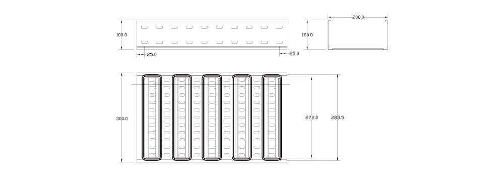
These values describe the product range. They do not mean every width, height, thickness and bottom design is available in every combination.
Use the approved product drawing to confirm dimensions, tolerances and connection details before ordering. A size table alone does not establish working load or maximum support span.
A dimension is useful only when its meaning is clear. Before comparing products, confirm how each manufacturer defines width, height and length.
A tray described as 300 × 50 × 3000 mm generally identifies:
| Measurement | Value | Meaning |
|---|---|---|
| Width | 300 mm | The stated transverse tray dimension |
| Sidewall height | 50 mm | The stated height of the tray sidewall |
| Section length | 3000 mm | The length of one straight section |
Material thickness should be stated separately, for example:
300 × 50 × 3000 mm, with 0.8 mm base metal thickness.
The drawing should clarify whether the width and height are nominal, internal or external measurements. Avoid assuming that a catalog dimension always describes clear cable space.
Nominal dimensions identify a product size for selection and ordering. Actual dimensions describe the manufactured component, subject to the specified tolerances.
A nominal value may also use a different measurement reference from the overall external dimension. This is a definition issue, not simply a manufacturing variation.
For example, a folded edge may extend beyond the stated tray width, or an inward-facing profile may reduce the clear opening.
Where a tray connects to equipment or an existing installation, confirm the actual interface dimensions rather than relying only on the nominal product name.
A useful drawing identifies the dimensions needed for cable arrangement, installation and component matching.
Include:
Installation drawings should also identify support locations and route clearances. Fitting drawings need the relevant angles, radii and connection dimensions.
Width selection begins with the cable arrangement. The required space depends on cable outside diameters, permitted grouping, separation and planned additions.
| Width — mm | Approximate Width — in |
|---|---|
| 100 | 3.94 |
| 150 | 5.91 |
| 200 | 7.87 |
| 300 | 11.81 |
| 400 | 15.75 |
| 500 | 19.69 |
| 600 | 23.62 |
| 700 | 27.56 |
| 800 | 31.50 |
The inch values are rounded conversions of the metric dimensions. They should not be interpreted as separate nominal inch-size products.
For example, 300 mm is approximately 11.81 inches; it is not exactly 12 inches.
Usable width is the clear space available for the intended cable arrangement. Overall width is the complete external footprint of the tray.
Sidewalls, folded edges, dividers and other internal features can affect the space available. Their influence depends on the actual profile.
Use usable dimensions to plan cable placement. Use overall dimensions to coordinate the route with walls, equipment, supports and other services.
When comparing two trays marked with the same nominal width, check both drawings. Identical labels do not necessarily mean identical internal space or interchangeable connections.
Start with each cable’s outside diameter and quantity. Establish the permitted arrangement, then account for any required separation, fixing components and defined expansion allowance.
Do not apply a universal fill percentage to every cable installation. The relevant rules depend on cable type, installation method and governing requirements.
Cable outside diameter, cable cross-sectional area and conductor cross-sectional area are different measurements. Use the measurement required by the selected sizing method.
Check the most congested parts of the route, including branches, transitions and equipment entries. A straight run that fits the cables may still need a different arrangement at its fittings.
One wide tray and several narrower routes can both be valid options.
| Consideration | What to Review |
|---|---|
| Cable separation | Whether compartments or independent routes are required |
| Thermal conditions | Cable grouping, loading and installation arrangement |
| Structural support | Combined weight, support geometry and available attachment points |
| Maintenance | Access to identify, add or replace cables |
| Available space | Overall width, vertical clearances and other services |
| Installation cost | Complete supports, fittings, labor and route complexity |
A single wide tray does not automatically cost less, and separate routes do not automatically solve thermal or interference concerns. Compare the complete arrangements.
Sidewall height influences the section geometry and available cable space. It should be selected with the cable arrangement and structural requirements.
| Sidewall Height — mm | Approximate Height — in |
|---|---|
| 50 | 1.97 |
| 100 | 3.94 |
Confirm the available combinations of height, width, thickness and bottom profile for the proposed product.
Sidewall height and usable loading depth are related, but they are not necessarily identical.
Top-edge folds, internal accessories, covers and bottom contours may affect the cable envelope. Check their actual geometry on the drawing.
Physical space also differs from permitted cable loading depth. A deeper tray does not automatically permit additional layers of power cables.
The allowable arrangement must satisfy the relevant cable installation and thermal requirements, even when more space appears available.
Review cable diameters, the intended grouping, dividers and cover requirements.
Also consider the surrounding installation space. A tall tray beneath a low ceiling may make cable laying or cover removal difficult.
Choose height as part of the complete route arrangement. It should provide the required cable space while preserving practical access for installation and maintenance.
Future additions should be defined in both space and weight. Extra sidewall height alone does not establish spare structural capacity.
Sidewall height affects the tray section, but it does not establish a working-load rating on its own.
Material properties, thickness, folded edges, bottom geometry, perforations, connections and support span all influence performance.
Compare documented load data for the actual configurations. Avoid assigning a load category solely because one tray has taller sides.
Section length describes the manufactured straight piece. It affects handling, joints and route planning, while support span describes a separate structural condition.
| Length — mm | Length — m | Approximate Length — ft |
|---|---|---|
| 2000 | 2.0 | 6.56 |
| 2500 | 2.5 | 8.20 |
| 3000 | 3.0 | 9.84 |
Metric and inch-based lengths should be specified accurately:
| Length in Feet | Exact Metric Conversion |
|---|---|
| 6 ft | 1828.8 mm |
| 8 ft | 2438.4 mm |
| 10 ft | 3048 mm |
A 3000 mm section is approximately 9.84 ft. It is 48 mm shorter than a 10 ft section.
This difference can matter when matching existing routes, equipment interfaces or project drawings.
A 3000 mm tray does not automatically permit supports spaced 3000 mm apart.
For example, a straight section supported at both ends and near its midpoint has a different structural arrangement from the same section supported only at its ends.
The permitted spacing must come from load data and installation instructions for the selected configuration. Joint position and support fixing also need review.
Specify section length and support span separately in the BOQ and technical submittal.
Longer sections can reduce joint quantities on suitable straight routes. They may also be harder to move through restricted entrances or position above equipment.
Shorter sections can suit access constraints, but may introduce additional connections.
Evaluate:
Select length for the complete installation rather than assuming the longest available piece is always the most efficient.
Bottom design should be reviewed when comparing internal space and matching components.
This configuration has a perforated base without additional stamped strengthening contours.
Its usable dimensions still depend on wall thickness, bends, folded edges and any internal accessories.
The absence of bottom reinforcement does not automatically define its load category or make it unsuitable for demanding applications. Review the complete configuration and relevant performance data.
Stamped ribs or contours change the base geometry and can affect the cable contact surface.
Their effect on internal clearance depends on whether the profile projects into the cable space and how it is formed. Do not assume every reinforcement pattern reduces width or depth by the same amount.
Bottom stiffening also does not automatically establish a longer permitted support span or justify reducing thickness. Those decisions need corresponding structural evidence.
Two trays marked 300 × 50 mm may differ in:
Check these details before approving a substitution or connecting new sections to an existing system.
Record cable type, quantity, outside diameter, weight per meter and minimum bend radius.
Identify where cables enter, leave or branch from the route. Define future additions and any separation requirements.
Establish the permitted grouping and layer arrangement before choosing tray dimensions.
Account for necessary spacing, fixing components and segregation. Where several cable types share a route, check each group’s requirements.
Compare the cable layout with the actual clear dimensions.
Include the effect of dividers, inward folds, covers and bottom profiles where relevant. Confirm installation access around the tray.
Select from 2000, 2500 or 3000 mm sections according to the route, handling conditions and connection requirements.
Keep section length separate from the structural support spacing.
Calculate cable weight using manufacturer data and account for planned additions and other applicable loads.
Compare the result with the working-load data on a consistent basis, confirming whether tray self-weight is included.
Check deflection, connections, supports and any concentrated loads as applicable.
IEC 61537 specifies requirements and tests for cable tray and cable ladder systems. Review relevant product data alongside the dimensions and support conditions required for your project.
6. Match Fittings and Accessories
Confirm bends, risers, tees, reducers, splice plates, covers and dividers against the selected profile.
Matching width and height alone does not guarantee compatibility. Check connection details, materials and finishes.
The following example demonstrates a width-selection method. It does not replace the electrical or structural design for a project.
Assume eight cables, each with an outside diameter of 25 mm, are arranged side by side in one layer.
Without spacing, their combined width is:
8 × 25 mm = 200 mm
This is the geometric width occupied by touching cables. It is not yet the required tray width.
For illustration, suppose the project arrangement requires:
The resulting layout width is:
200 + (7 × 10) + 20 = 290 mm
These allowances are example assumptions, not universal installation requirements.
A nominal 300 mm tray would be a candidate only if its verified usable width accommodates the 290 mm arrangement. Otherwise, evaluate the next suitable size.
Any future cable allowance must be assessed separately.
Before confirming the size, review:
The width calculation provides a shortlist. The remaining checks determine whether the configuration is suitable.
| Mistake | Better Approach |
|---|---|
| Treating nominal width as clear width | Check the product drawing and usable space |
| Treating sidewall height as permitted loading depth | Verify internal geometry and cable arrangement rules |
| Using section length as support span | Specify and verify both separately |
| Calling 3000 mm exactly 10 ft | Use accurate conversions and ordering dimensions |
| Applying one fill percentage to all cables | Use the relevant installation requirements |
| Selecting by thickness or height alone | Review the complete structural configuration |
| Allowing space without checking added weight | Assess expansion in both dimensions and load |
| Assuming equal sizes mean interchangeable parts | Check profiles, joints, holes and covers |
Custom dimensions may be worth evaluating where standard sections do not fit equipment interfaces, restricted spaces or an existing route.
Before requesting customization, check whether a standard size with a suitable fitting or revised layout can meet the requirement.
Changes to width, height, thickness, perforations or reinforcement may affect the applicability of existing load data. Confirm what additional review is needed.
| Item | Information to Provide |
|---|---|
| Tray dimensions | Width × sidewall height × section length |
| Measurement definition | Nominal, usable and overall dimensions as needed |
| Material thickness | Base metal thickness and required tolerance |
| Bottom design | With or without stamped bottom reinforcement |
| Material and finish | Grade, coating and exposure requirements |
| Cable information | Quantities, outside diameters and weight per meter |
| Support conditions | Proposed span, fixing method and joint locations |
| Fittings | Dimensions, angles, radii and quantities |
| Accessories | Covers, dividers, connections and supports |
| Drawings | Route, clearances and equipment interfaces |
| Documentation | Required drawings, performance data and certificates |
| Delivery | Quantities, destination and schedule |
A request such as “300 mm cable tray” leaves the height, length, thickness, material and structural requirements undecided.
A complete RFQ makes supplier proposals easier to compare.
ECTRAY provides perforated cable tray configurations in different widths, sidewall heights, lengths and bottom designs.
For a useful review, send your cable schedule, route drawings, required clearances and proposed support span. These details help identify a suitable dimensional configuration and the fittings needed to complete the route.
Explore ECTRAY’s perforated cable tray range for product options.
Share your BOQ and installation requirements with ECTRAY to discuss dimensions, compatible components and a project quotation.
Sizes vary by manufacturer. ECTRAY’s range includes widths of 100–800 mm, sidewall heights of 50, 100, 150 and 200 mm, and section lengths of 2000, 2500 and 3000 mm. Confirm the available combinations for the selected configuration.
Start with cable quantities and outside diameters. Establish the permitted arrangement, then account for required spacing, dividers, fixing components and planned additions. Compare that layout with the tray’s verified usable width.
Not necessarily. Nominal width identifies the stated product size. Usable width is the clear space available for the intended cable arrangement. Check the drawing to understand the measurement reference.
Sidewall height describes the wall geometry. Available internal depth may be affected by folds, covers and bottom contours. Permitted cable loading depth also depends on the applicable installation requirements.
No. A 10 ft section is 3048 mm long. A 3000 mm section is approximately 9.84 ft and is 48 mm shorter.
No. Support spacing depends on the selected configuration, load, joints and installation conditions. A long section may require intermediate supports.
They may share nominal dimensions while differing internally. Review bottom contours, folded edges, clearances and connection details before treating them as interchangeable.
Custom dimensions can be evaluated against manufacturing capability and project requirements. Provide drawings, cable information and support conditions so the proposed configuration and documentation needs can be reviewed.

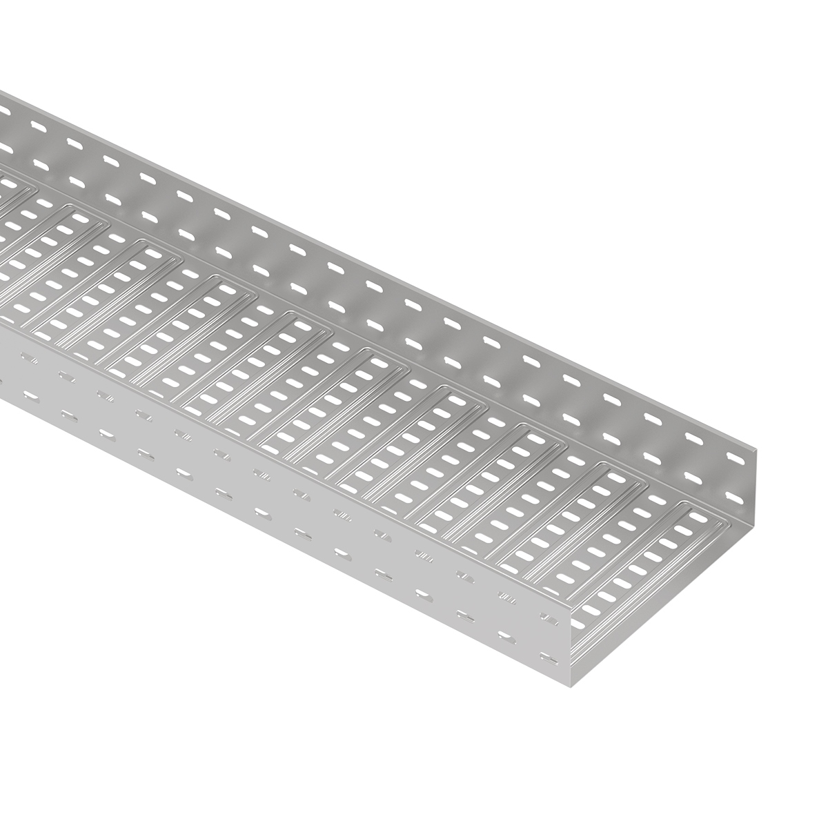
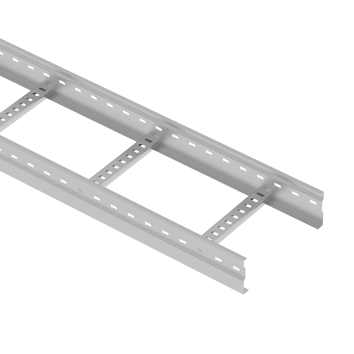
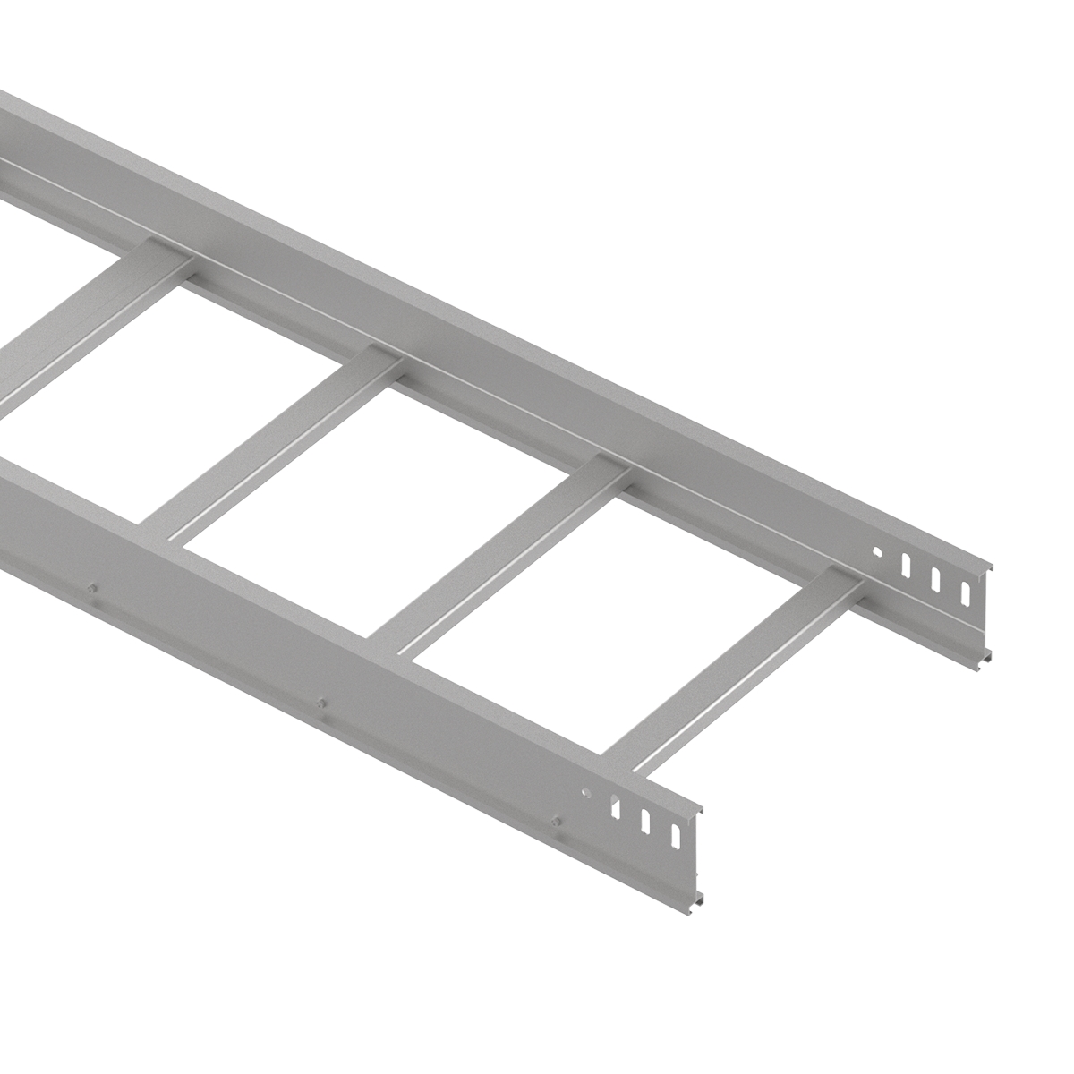
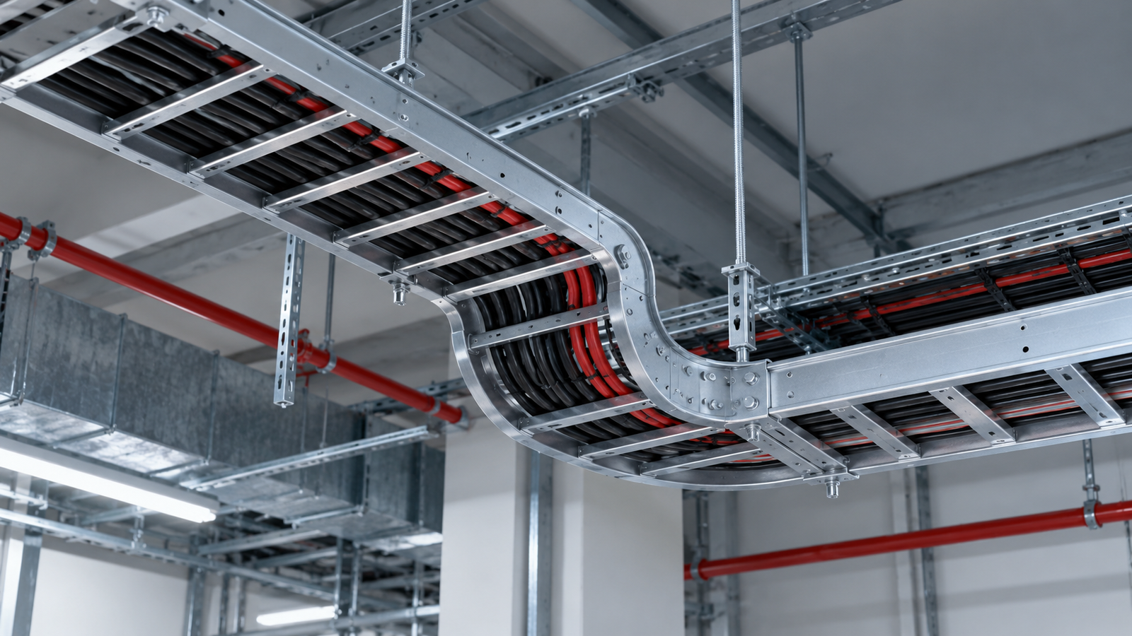

[…] ZM Perforated Cable Tray […]
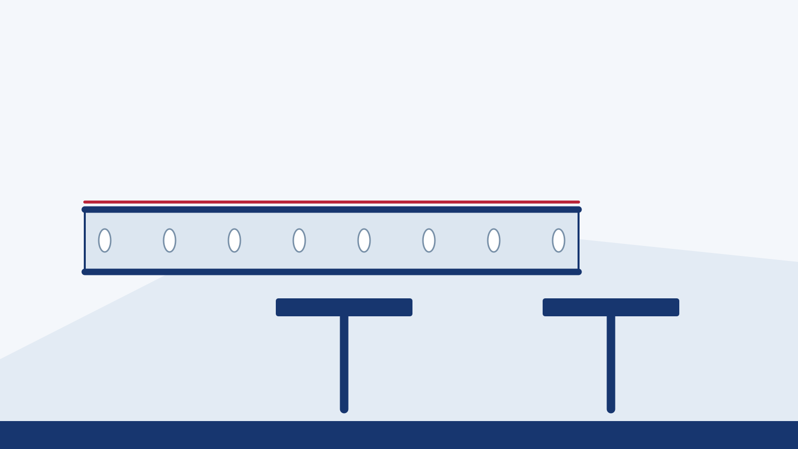
[…] Tray width, height, thickness and profile. […]
[…] Overall Tray Width vs Reinforcement Width […]