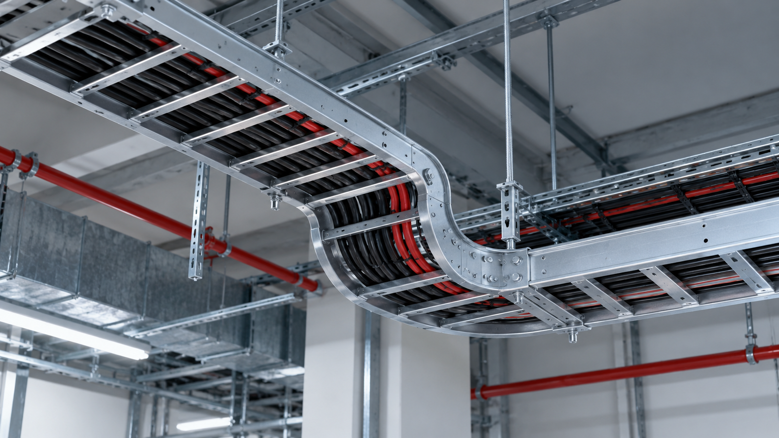
Perforated cable tray drawings help engineers, buyers and installers understand a product before manufacturing or installation. They communicate the tray profile, overall dimensions, reinforcement layout and perforation details.
Reading a drawing requires identifying both the dimension and the feature it measures. Overall tray width, reinforcement width, flange width and hole spacing describe different parts of the product.
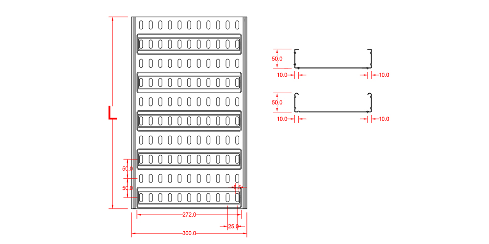
This guide uses an ECTRAY reinforced perforated cable tray as a practical example. The supplied drawing shows a 300 mm overall tray width, 50 mm height and 272 mm bottom reinforcement width.
ECTRAY has also separately confirmed a 10 mm flange width and an available sheet thickness range of 0.6–1.5 mm. These additional specifications should be distinguished from dimensions shown in the supplied image.
Different views explain different aspects of the product. Read them together to understand how the dimensions and features relate to one another.
| Drawing view | Information to review |
|---|---|
| Plan view | Overall width, length direction, perforations and reinforcement layout |
| Cross-section view | Tray height, sidewall profile and local formed details |
| Side view | Longitudinal features and end details where shown |
| Detail view | Enlarged folds, reinforcement, holes or connection geometry |
| Assembly view | Relationship between the tray and matching components |
The plan view shows the tray from above.
In the supplied example, 300 mm identifies the overall tray width, while 272 mm identifies the width of the stamped bottom reinforcement.
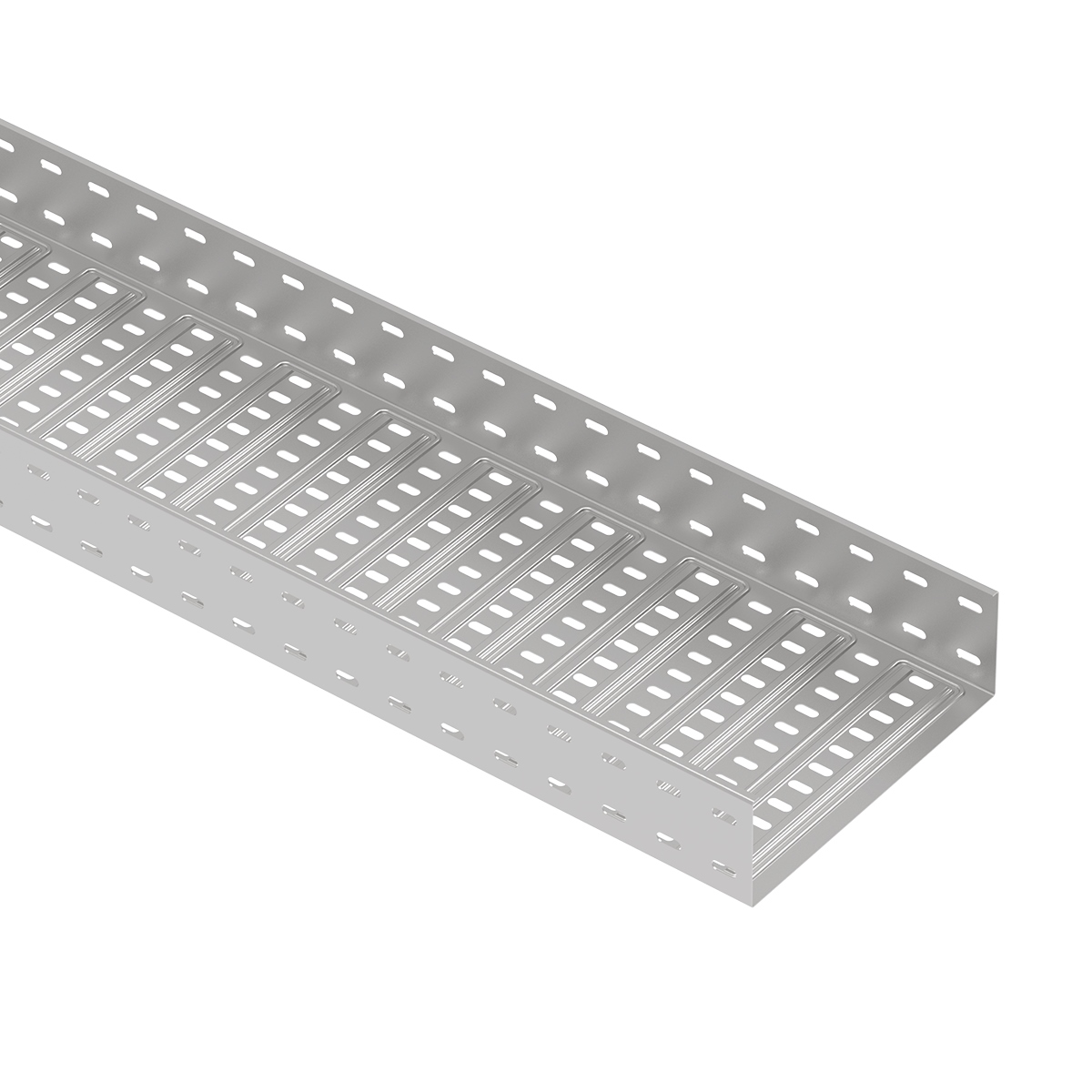
The plan view also shows repeated reinforcement features and the perforation arrangement along the tray length.
The 272 mm reinforcement width belongs to this illustrated 300 mm wide configuration. Other tray widths require their own confirmed reinforcement dimensions.
The cross-section shows the tray profile across its width.
Use it to identify the base, sidewalls, folded edges and local profile details. The supplied example includes a 50 mm tray height and a 10 mm reinforcement-to-sidewall distance at the indicated location.
The separately confirmed 10 mm flange width is not dimensioned in this image.
This distinction is important: a visible profile feature and a confirmed specification are not necessarily the same as a dimension explicitly shown on the drawing.
A product can be defined through both drawing dimensions and accompanying specifications.
Before reviewing individual measurements, check the product model, units, drawing number and revision. Then identify any information supplied separately, such as sheet thickness, flange width, material grade or finish.
For an approved order drawing, these sources should agree and clearly identify the required configuration.
A professional drawing review separates information read directly from the drawing from information confirmed elsewhere.
For this ECTRAY example, the distinction is as follows:
| Item | Value | Information source |
|---|---|---|
| Overall tray width | 300 mm | Shown in the supplied drawing |
| Tray height | 50 mm | Shown in the supplied drawing |
| Bottom reinforcement width | 272 mm | Shown in the plan view |
| Reinforcement-to-sidewall distance | 10 mm | Shown at the indicated section location |
| Hole diameter | Ø8.5 mm | Dimension meaning confirmed by ECTRAY |
| Transverse hole center spacing | 25 mm | Dimension meaning confirmed by ECTRAY |
| Longitudinal hole row center spacing | 50 mm | Dimension meaning confirmed by ECTRAY |
| Tray length | L | Variable shown in the drawing |
| Flange width | 10 mm | Separately confirmed; not dimensioned in the supplied image |
| Available sheet thickness | 0.6–1.5 mm | Separately confirmed manufacturing range |
The flange width should be added to the applicable order drawing or associated specification where it is needed for manufacturing, inspection or accessory matching.
The 300 mm and 272 mm dimensions describe different features.
The 300 mm dimension identifies the overall width of the illustrated tray.
It describes the external product width between the indicated reference points. It should not automatically be treated as the clear space available for cables.
Where internal clearance is required, check a separately defined internal dimension.
The ETIM cable tray dimensional model identifies overall and internal dimensions separately. Check which measurement is specified before comparing tray sizes.
The 272 mm dimension in the plan view identifies the width of the stamped bottom reinforcement.
It does not represent the overall tray width or internal clear width.
The correct description is:
A 300 mm wide perforated cable tray with a 272 mm bottom reinforcement width in the illustrated plan view.
Keeping these measurements separate prevents a local feature dimension from being mistaken for a product size.
The 272 mm reinforcement width applies to the illustrated 300 mm wide configuration.
Do not transfer it to every tray width or scale it proportionally without confirmation.
When reviewing perforated cable tray drawings for another size, use the corresponding product drawing and reinforcement dimensions.
This example includes two different measurements with the same numerical value.
One is shown in the supplied drawing. The other was confirmed separately.
The existing 10 mm dimension in the cross-section identifies the reinforcement-to-sidewall distance at the indicated location.
Read it using the reference points shown.
Do not replace it with a distance calculated by subtracting the 272 mm reinforcement width from the 300 mm overall width. Overall and local dimensions can reference different surfaces or feature boundaries.
Where these dimensions need to be checked together, use a detailed section with clearly defined reference points.
ECTRAY has separately confirmed a 10 mm flange width.
This dimension is not marked in the supplied image. It should therefore be described as an additional product specification, rather than a measurement read from the screenshot.
For manufacturing or inspection, include the flange width in the approved drawing or associated specification.
The two measurements should remain separately identified:
| Measurement | Value | Status |
|---|---|---|
| Reinforcement-to-sidewall distance | 10 mm | Dimensioned in the supplied drawing |
| Flange width | 10 mm | Separately confirmed; not dimensioned in the supplied image |
An identical value does not mean two dimensions describe the same feature.
In this guide, a flange means the folded edge of the tray profile. It should be distinguished from an end connection flange used in another design.
Trace the section from the base along the sidewalls and folded edges.
Check the fold direction and whether the profile includes an additional return fold. Where the general view is unclear, request an enlarged detail.
The separately confirmed flange width for this example is 10 mm. The original image should not be presented as showing that dimension.
One width measurement does not fully define a folded profile.
Depending on the intended use of the drawing, additional information may be required for bend geometry, fold direction, return folds and dimensional tolerances.
These details are particularly useful where the folded edge interfaces with another component.
Where a cover or clamp is required, compare its interface with the actual tray profile.
Review the flange geometry, cover dimensions and fixing arrangement together. Nominal tray width alone does not define the complete assembly.
An assembly section can clarify the relationship between the tray, cover and fixing components.
Height, length and thickness should be clearly assigned in the product documentation.
The section drawing specifies a 50 mm tray height.
This should be distinguished from usable internal depth. The base profile, folds and any features extending into the cable space need to be considered when defining internal clearance.
The supplied image does not fully establish the reinforcement height or forming direction. Confirm those details where internal depth needs to be assessed.
The symbol L represents manufactured tray length.
Its value should be assigned in the drawing notes, specification or order schedule. Do not estimate it from the displayed proportions of the image.
Tray length and support span are different:
| Term | Meaning |
|---|---|
| Tray length | Length of one manufactured tray section |
| Support span | Distance between supports carrying the installed tray |
A specified tray length does not establish an allowable support span.
ECTRAY manufactures this reinforced tray design in sheet thicknesses from 0.6 to 1.5 mm.
This range describes available manufacturing options. Each order requires an exact selected thickness.
| Specification | Information to confirm |
|---|---|
| Available thickness range | 0.6–1.5 mm |
| Order thickness | Exact selected sheet thickness |
| Material | Required material grade |
| Surface finish | Specified coating or treatment |
| Measurement basis | Clarification of coating inclusion where applicable |
The range should not be used in place of an order-specific value.
The plan view shows repeated transverse reinforcement features along the tray base.
It explains their layout, while additional sections may be needed to define the formed profile completely.
Find the repeated formed outlines in the plan view.
For this 300 mm wide tray, the reinforcement width is 272 mm.
Keep that dimension associated with the reinforcement feature. It should not be relabeled as internal width or flange width.
A plan outline does not fully establish reinforcement height or forming direction.
A local section should clarify:
These details connect the plan view with the actual manufactured shape.
To compare a reinforced tray with a tray without bottom reinforcement, use equivalent views and consistent dimension definitions.
Record overall dimensions, sheet thickness, folded profile, reinforcement geometry and perforation pattern separately.
Drawings explain structural differences. A comparison of working loads requires supporting information for the relevant configurations and support conditions.
Hole size and hole position describe different aspects of the perforation pattern.
A diameter defines the size of the indicated hole. Center-to-center spacing defines the position of one hole relative to another.
ECTRAY has confirmed that the 8.5 mm dimension specifies hole diameter.
In written specifications, it can be expressed as Ø8.5 mm. The diameter symbol distinguishes hole size from a linear spacing measurement.
The callout should clearly identify the feature to which the diameter applies. It should not be described as hole spacing or a hole-to-edge distance.
The 25 mm dimension is the center-to-center distance between adjacent holes across the tray width.
It describes positioning rather than the clear gap between hole edges.
It also does not describe the distance from a hole center to the tray edge.
The 50 mm dimension in the plan view describes the center-to-center spacing between adjacent hole rows along the tray length.
It should be distinguished from the separate 50 mm tray height dimension.
| Dimension | Meaning |
|---|---|
| Ø8.5 mm | Diameter of the indicated hole |
| 25 mm | Transverse hole center-to-center spacing |
| 50 mm in the plan view | Longitudinal hole row center-to-center spacing |
| 50 mm in the cross-section | Tray height |
The numerical value alone does not establish meaning. Read the associated view and dimension references.
Hole spacing measures the relationship between holes.
Edge distance locates a hole relative to a defined product edge.
In this example, 25 mm is hole center-to-center spacing. Any required hole-to-edge position needs its own dimension or an explicitly defined positioning scheme.
A structured review helps separate overall dimensions, local features and additional specifications.
Identify the 300 mm overall width and 50 mm height shown in the drawing.
Locate L and check the associated documentation for its assigned value.
Keep overall dimensions separate from internal clearances and reinforcement dimensions.
Locate the 272 mm reinforcement width in the plan view.
Then review the drawing’s 10 mm reinforcement-to-sidewall distance using its indicated reference points.
Confirm that the drawing corresponds to the required tray width before applying these dimensions.
Record the separately confirmed 10 mm flange width.
Because it is not dimensioned in the supplied image, add it to the order drawing or supporting specification where required.
Do not identify the existing 10 mm drawing callout as flange width.
Read Ø8.5 mm as hole diameter.
Read 25 mm as transverse hole center-to-center spacing and 50 mm as longitudinal hole row center-to-center spacing.
This separates the size of the indicated hole from its position within the pattern.
Select the exact sheet thickness within the available 0.6–1.5 mm range.
Then confirm any required information not established by the image, including:
A drawing review should record both confirmed information and unresolved requirements.
Perforated cable tray drawings should be reviewed with the components needed to join and complete the route.
Compare tray end details with the matching splice plate drawing.
Check hole dimensions, center spacing, distance from the tray end and specified fasteners.
The bottom perforation arrangement should not be assumed to define the end connection pattern.
Review fixing positions against the actual tray profile.
Check for interference with folded edges, reinforcement features and connection hardware.
An assembly drawing is useful where several parts share the same fixing area.
For fittings, confirm the interface dimensions at each connection.
Review widths, heights, directions and joint details together. Matching nominal sizes should be checked against the actual profile and connection arrangement.
The 300 mm dimension describes overall tray width.
The 272 mm dimension describes reinforcement width in the plan view. It does not establish internal clear width.
The existing 10 mm drawing dimension identifies reinforcement-to-sidewall distance.
The separately confirmed 10 mm flange width is not dimensioned in the supplied image.
Keep their descriptions and information sources separate.
A confirmed product specification can be valid even when it is absent from an illustration.
However, the article, quotation and inspection documents should state whether the information comes from the drawing or an additional specification.
The 272 mm value belongs to the illustrated 300 mm wide configuration.
Other widths require their own confirmed dimensions.
Ø8.5 mm describes hole size.
The 25 mm and 50 mm perforation dimensions describe center-to-center positioning.
The 0.6–1.5 mm range describes available manufacturing options.
Each order requires an exact selected thickness.
A screenshot may be resized, cropped or displayed at an unknown scale.
Use stated dimensions and approved drawing data. Request missing measurements rather than estimating them from the image.
A drawing describes product geometry.
It does not independently establish an allowable working load at a proposed support span. Review the relevant material, thickness, support conditions and performance documentation before making a load claim.
For cable tray and cable ladder system requirements and testing, consult IEC 61537. The standard reference alone does not establish the load capacity of the illustrated product.
| Review item | Information to confirm |
|---|---|
| Drawing identification | Model, drawing number, revision and approval status |
| Units | Applicable units and any exceptions |
| Overall dimensions | Width, height and assigned length |
| Internal clearances | Clear width and depth where required |
| Sheet thickness | Exact selected thickness |
| Material and finish | Required grade and surface treatment |
| Drawing dimensions | Features and measurement references clearly identified |
| Additional specifications | Separately confirmed values incorporated where required |
| Flanges | Width and complete geometry where required |
| Reinforcement | Dimensions applicable to the selected tray width |
| Hole size | Diameter and complete geometry of each opening type |
| Hole positioning | Center-to-center spacing and required edge distances |
| Connections | End holes, splice plates and fasteners |
| Accessories | Matching covers, dividers and fittings |
| Tolerances | Acceptance limits for relevant dimensions |
| Performance | Separate information for the intended load and support arrangement |
The objective is a consistent product definition that purchasing, manufacturing and inspection can follow.
ECTRAY offers perforated cable tray designs with and without stamped bottom reinforcement.
Reinforced designs are available in sheet thicknesses from 0.6 to 1.5 mm. Dimensions, flange details and reinforcement geometry should be confirmed for the selected configuration.
For a quotation or drawing review, provide:
Share your drawing or marked-up specification with ECTRAY to clarify the product profile and matching components before ordering.
The supplied drawing shows a tray with a 300 mm overall width and a 50 mm height.
It identifies the bottom reinforcement width in the plan view of the 300 mm wide tray. It does not represent internal clear width.
It identifies the reinforcement-to-sidewall distance at the indicated location.
No. ECTRAY separately confirmed a flange width of 10 mm. It is not dimensioned in the supplied image and should be added to the applicable order documentation where required.
No. The 272 mm value applies to the illustrated 300 mm wide configuration. Check the corresponding drawing for other widths.
The available sheet thickness range is 0.6–1.5 mm. The exact order thickness should be specified separately.
It specifies the diameter of the indicated hole.
It is the center-to-center distance between adjacent holes across the tray width. It is not a hole-to-edge distance or a clear gap between hole edges.
The cross-section uses 50 mm for tray height. The plan view uses 50 mm for longitudinal hole row center-to-center spacing.
No. L represents manufactured tray length. Support span is the distance between installed supports.
No. A working load assessment also requires the relevant material, sheet thickness, support conditions and performance documentation.