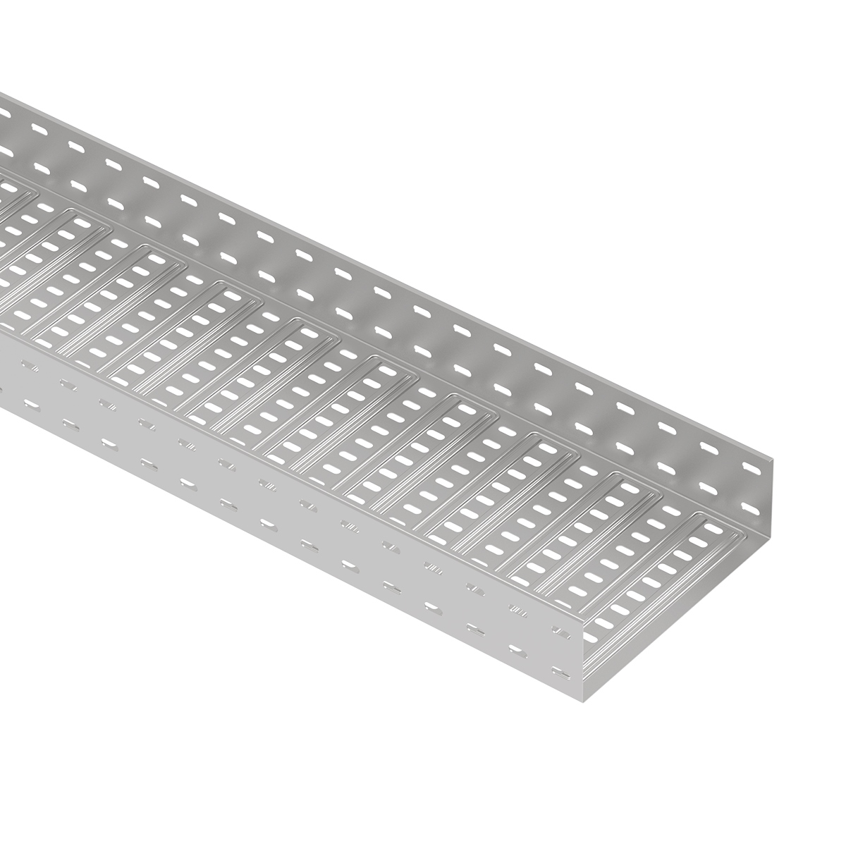
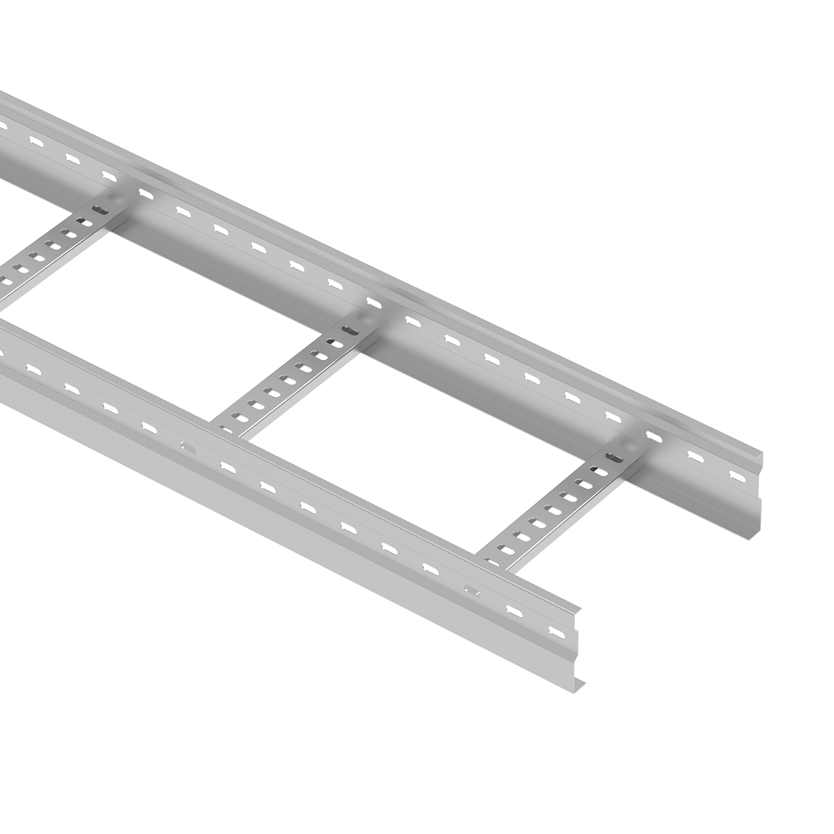
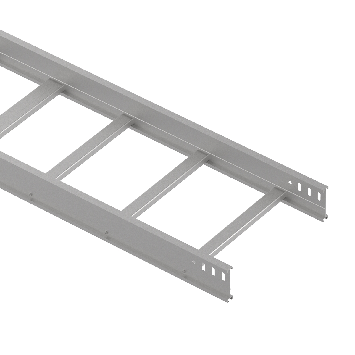
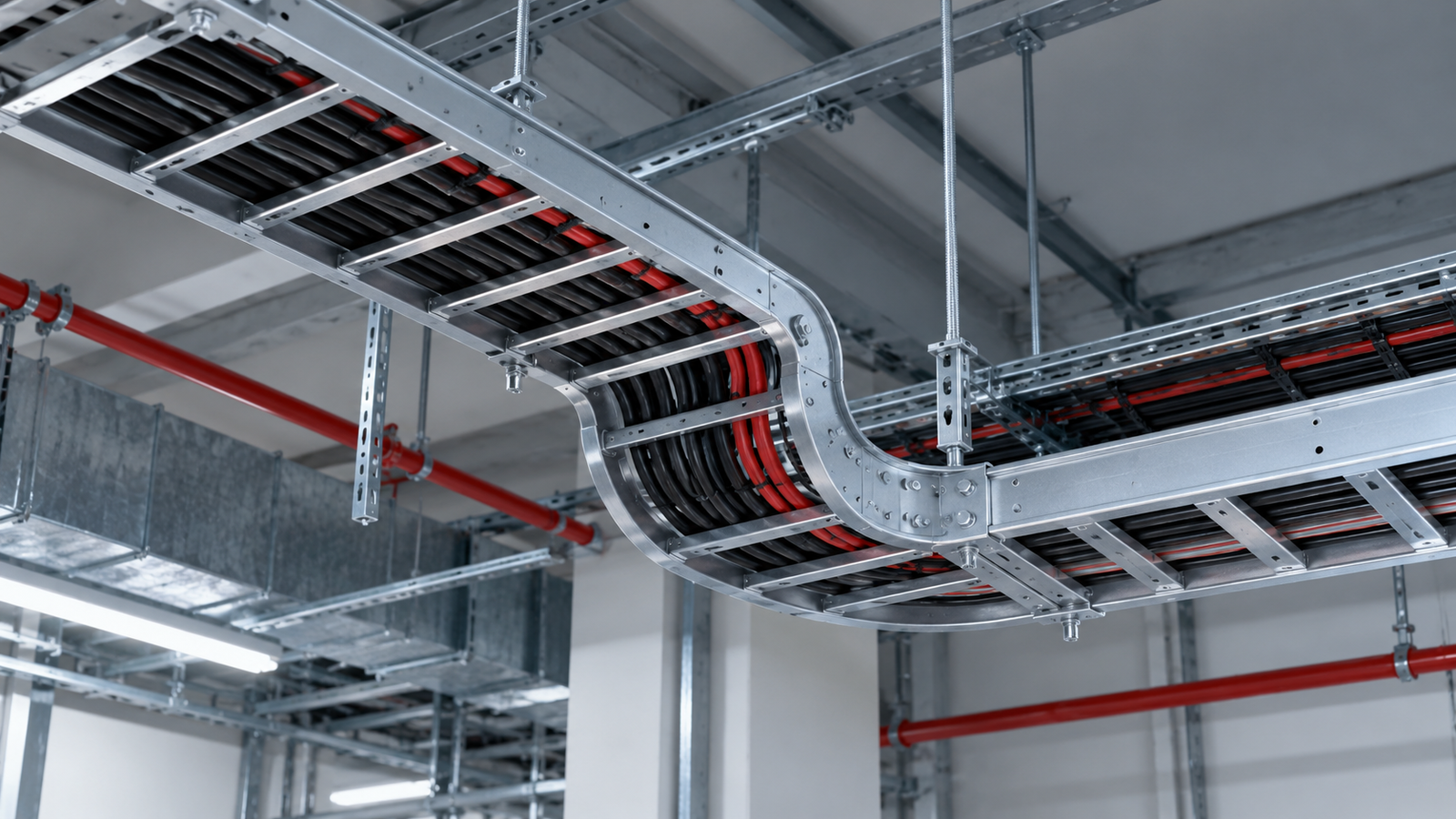
A cable ladder expansion joint allows a defined part of a ladder run to change length without forcing that movement into an ordinary rigid splice, support or building connection. Selecting the joint is only one part of the decision. A workable detail also needs a calculated movement allowance, a deliberate fixed-point and guide arrangement, cable allowance, electrical continuity and a setting that matches the temperature when the joint is installed.
If a long route crosses a warm plant room, a cool outdoor zone and a building movement joint, those are not necessarily one problem with one accessory solution. The designer must identify which movements the ladder is expected to accommodate and where they can occur. This guide follows that sequence from route assessment to installation inspection. It does not prescribe a universal joint spacing, gap, torque or bonding conductor for an ECTRAY system; those values require the selected manufacturer's detail and project design.
Cable ladder changes length as its temperature changes. The likely movement depends on the material's expansion behaviour, the length of the free-moving segment and the range between the temperatures relevant to that segment. A roof run exposed to sun and cold may experience a different range from a short run inside a controlled room. The ladder's installation temperature matters too, because the joint must have travel available in the direction in which the run will move after installation.
Movement can also come from the structure rather than the ladder material. A route crossing a building expansion joint or connecting structures with different movements needs its own coordination with the structural and electrical design. A ladder accessory chosen for thermal growth should not automatically be treated as proof that the entire crossing can accommodate structural displacement in every direction.
Begin with the route drawing, materials and site conditions. Identify long continuous runs, changes in exposure and structural joints. Then compare the expected displacement with the travel of the proposed ladder connection and the position of supports, guides and fixed points. If the movement assumptions are missing, the defensible next step is to obtain them, not to copy a nominal joint interval from another manufacturer's example. Cable Tray Institute guidance and manufacturer installation literature both treat expansion and restraint as a system-level layout question.
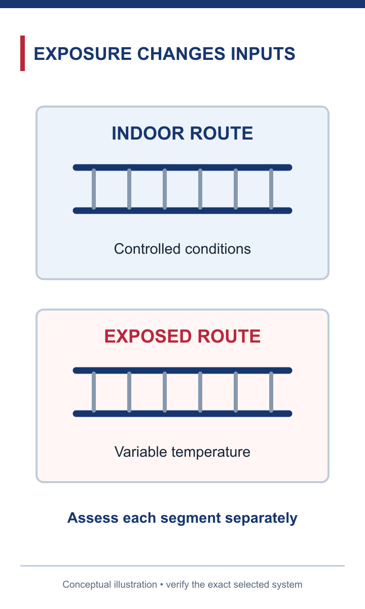
Conceptual side by side; verify the exact selected system.
An ordinary splice joins adjacent ladder lengths so the assembled route maintains its intended mechanical continuity. An expansion connection must also permit a specified relative movement between those lengths. That difference affects its geometry, fasteners, installation setting and nearby support arrangement. A slotted or sliding component should be used in the way its manufacturer specifies; a similar-looking plate cannot be assumed to have the same travel or load behaviour.
The distinction is especially important when a bill of materials says only “splice plate”. Procurement may substitute a rigid connector for a movement detail or a movement connector where a rigid structural joint was intended. Ask for the exact ladder series, compatible expansion accessory, dimensioned connection drawing and installation instruction. Check whether the selected assembly needs a separate bonding jumper or other continuity provision. Product pages may confirm that expansion couplers exist, but the project still needs evidence for the particular joint and its movement range.
A joint also does not work in isolation. If supports or hold-downs on both sides restrain the ladder against lengthwise movement, a correctly selected expansion component can be defeated by the installation. Conversely, leaving every support free to slide may remove a fixed reference that the manufacturer's layout requires. Treat the connector and the restraint plan as one drawing review.
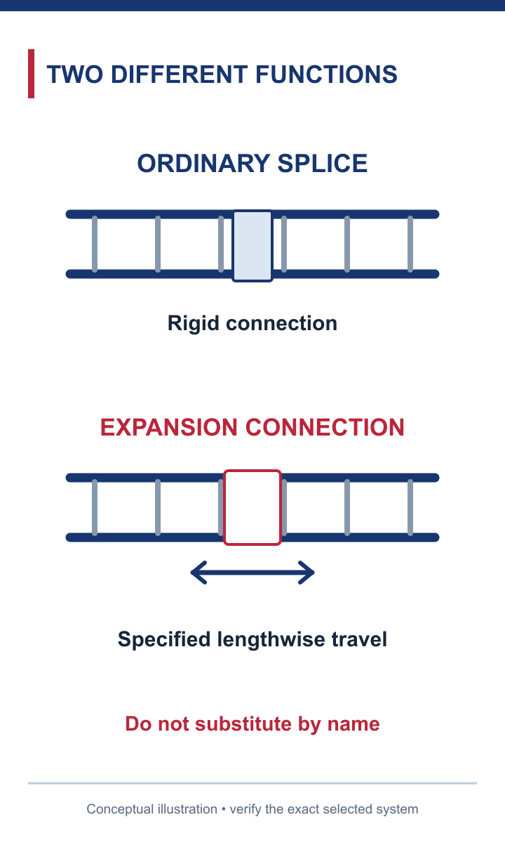
Conceptual mechanism; verify the exact selected system.
Use a staged calculation and setting process rather than starting with a convenient visible gap:
This process prevents a common error: a joint that looks open at handover but reaches the end of its travel during a later temperature swing. The opposite setting error can leave too little movement for cooling. A measured opening has meaning only when paired with the exact joint, design movement and installation condition. Do not infer a safe gap from a catalogue photograph.
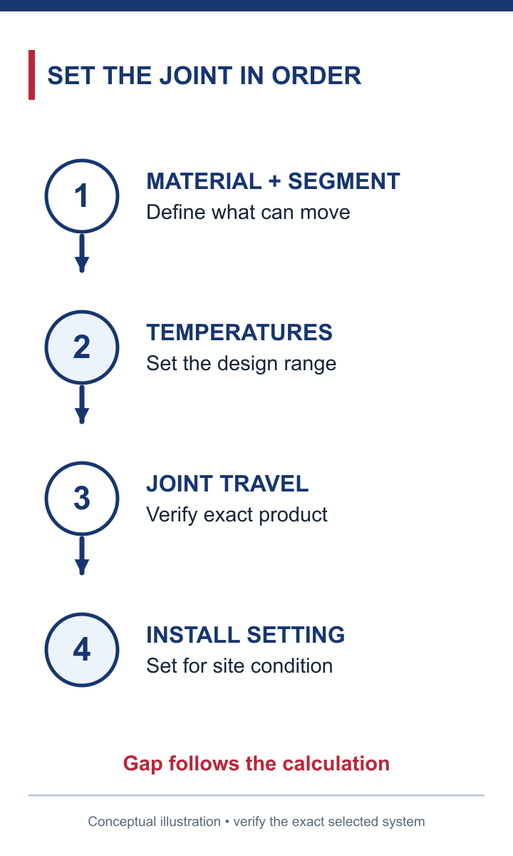
Conceptual process flow; verify the exact selected system.
A fixed point establishes where a moving ladder segment is restrained. Guides control the route's alignment while permitting the intended longitudinal travel. Supports carry load; they do not automatically provide the right movement function. The design should label these functions separately, because the same piece of steelwork can be installed as a rigid clamp or a sliding guide depending on the detail used.
Place the expansion connection and nearby supports according to the selected system's instructions and the route design. The guide arrangement must keep the ladder properly supported and aligned without binding at the joint. A support located in the wrong place can add bending or make the coupler carry a duty that its installation detail did not contemplate. When several joints occur on one route, define the fixed and moving segments so that their travel does not conflict.
Check changes of direction, drops, covers, branch connections and attached equipment as well. Any of these may act as an unintended restraint if the ladder is expected to move through them. At a building joint, coordinate the ladder movement detail with cables, fire stopping and other services rather than solving only the visible ladder connection. The approved route drawing should show the movement path clearly enough for installers and inspectors to verify it.
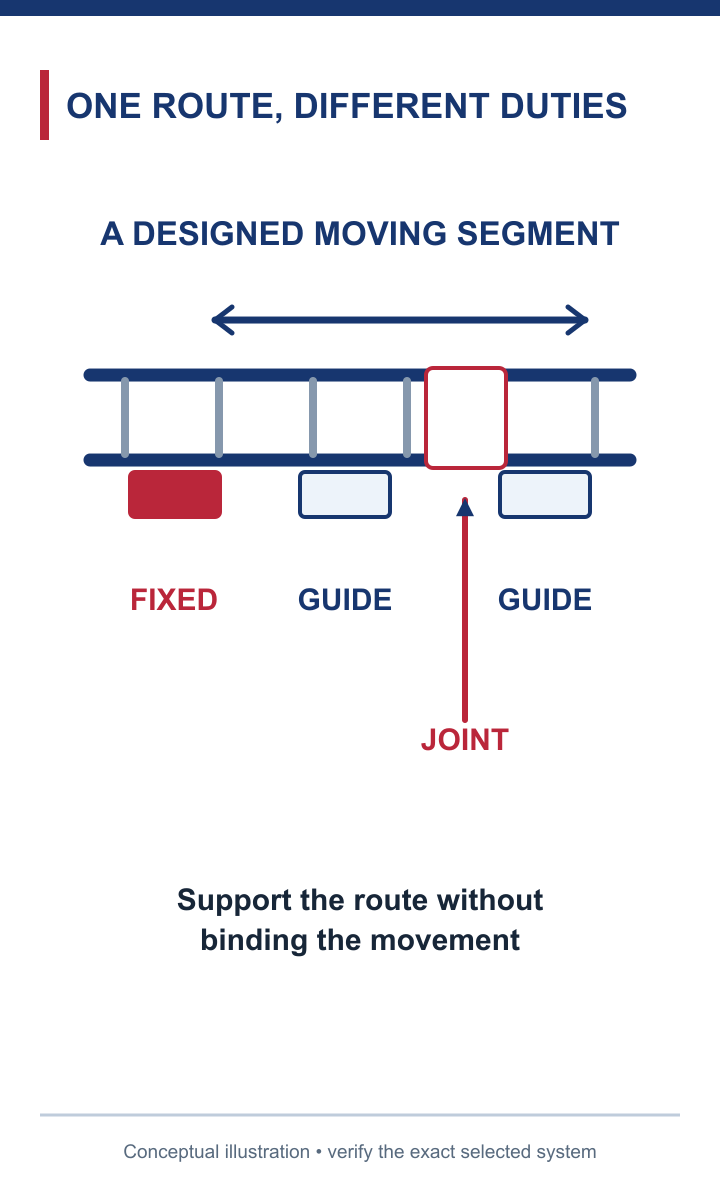
Conceptual system map; verify the exact selected system.
Where the cable-support system forms part of the electrical continuity or protective bonding arrangement, a moving joint needs a verified continuity detail. A mechanical connection that slides is not automatically a dependable electrical path for the project's duty. Follow the electrical designer's requirements and the selected manufacturer's instructions for the appropriate bonding component, termination and inspection method. This guide does not assign a universal jumper size or claim that any accessory has a particular fault-current performance.
The cables also need room to tolerate the ladder's expected movement. A cable pulled tight across a joint may transfer force to its terminations or be damaged as the ladder changes length. Equally, arbitrary excess cable or a tight bend may create a different installation problem. Coordinate cable type, bend limits, cleating or restraint, and the movement direction with the cable designer and manufacturer's guidance. The ladder joint, bonding detail and cable allowance should be visible together on the same installation review.
Inspect the finished assembly with these separate questions in mind: can the joint travel, is the specified bonding provision present and protected, and do the cables have the designed allowance without interference? A photograph of a jumper alone cannot prove the movement clearance or the electrical rating. Keep the model-specific product documentation and the project electrical detail with the inspection record.
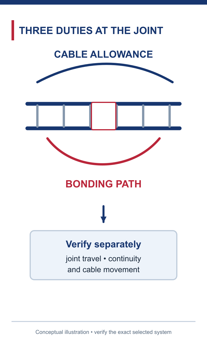
Conceptual annotated object; verify the exact selected system.
Start with the exact ladder series and side-rail profile. Confirm the rail height, flange shape, material, finish and splice-hole pattern against the proposed joint drawing. Check whether the connector is designed for that ladder family and whether its fastener set, cover and support details are included. An accessory described generically as a “cable ladder expansion joint” may not fit a different manufacturer's rail even when its nominal width looks similar.
Next specify the environmental and structural context. The ladder and joint finish must suit the exposure, and any dissimilar-metal or coating detail should be reviewed as an assembly. Ask for the usable movement range, installation setting procedure, nearby support requirements, bonding provision and inspection criteria for the exact product. A claimed rating, approval or load capacity belongs to a documented model and test or calculation basis, not to the accessory category as a whole.
An RFQ is stronger when it includes a small movement schedule: route location, ladder series, free segment length, material, design temperature assumptions, expected travel, installation condition, fixed-point locations and required continuity detail. That gives a supplier enough context to confirm compatibility or identify an unresolved design input. It also makes proposed substitutions reviewable before the joint is purchased or installed.
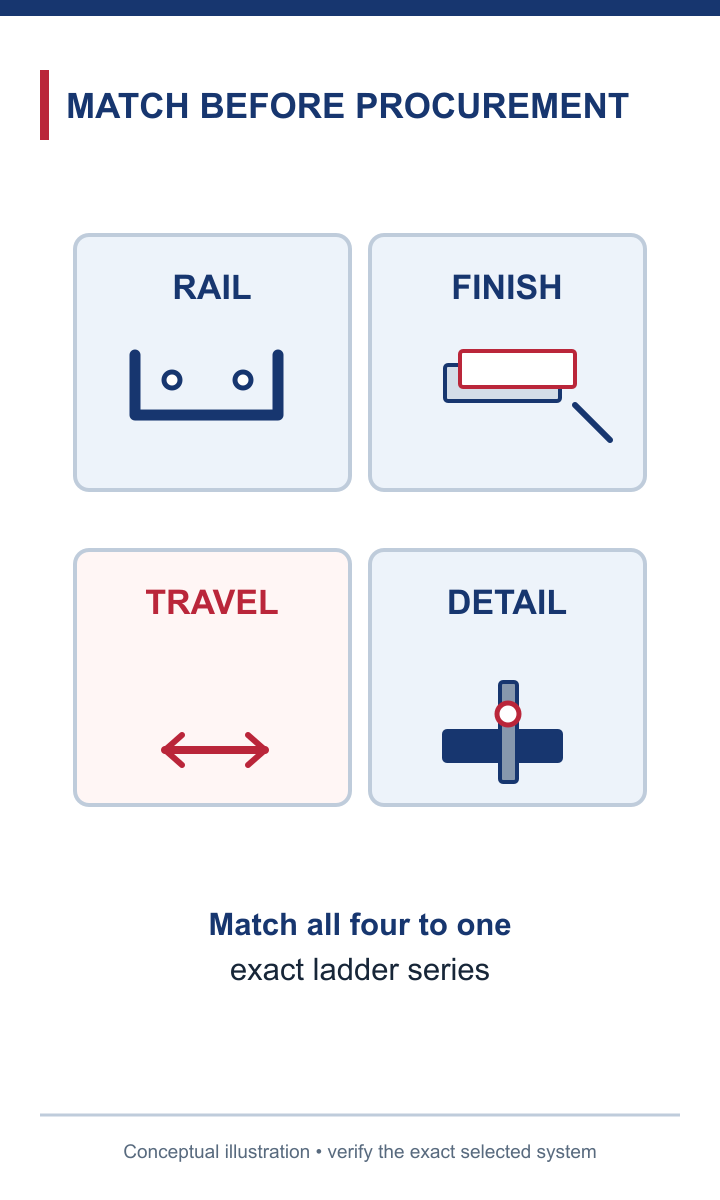
Conceptual comparison matrix; verify the exact selected system.
ECTRAY's cable-ladder installation guidance provides a customer-specific starting point for discussing joints, supports and installation details. Yuchang's approved customer information describes technical selection support based on project loads, spans, installation conditions and environment. It does not, by itself, establish a particular expansion accessory's travel, electrical rating or universal fit.
Send the ECTRAY ladder series, rail drawing, route and support layout, design temperatures, movement calculation and the intended fixed and guided points. Ask for the compatible joint reference and dimensioned drawing, its documented usable travel, setting instructions, fastener list, support arrangement and bonding detail. If the project needs a specific approval, test or fault-duty statement, request evidence for the exact model rather than assuming the general installation guide covers it.
The useful output is a product-specific movement detail that a buyer can procure and an installer can check. If the ladder model or movement data are still unknown, mark the joint selection provisional. The next action is to settle those inputs with the designer and ECTRAY technical team before treating a catalogue image as an approved connection.
Before installation, compare the delivered joint and fasteners with the approved schedule. Confirm the ladder series and rail profile, inspect coatings and check that support and fixed-point locations match the latest drawing. Marking the intended guide locations before placing the ladder reduces the risk that a crew later tightens every support as a rigid hold-down.
At the joint, follow the manufacturer's sequence and setting procedure. Measure the relevant installation temperature, set the opening or joint position from the approved detail, and verify that the connection can move in the required direction without binding. Install any specified bonding provision and cable allowance as separately detailed. Do not adopt torque values or support distances from another system simply because its joint looks similar.
The final check is an as-built movement audit, not just a fastener count. Record the joint model, setting, installation condition, fixed and guided supports, continuity provision and cable clearance. Look for fouling at covers, branches, walls and penetrations. If a support was moved or a different accessory used, revise the movement review before accepting the installation. An accessible inspection record helps maintenance teams avoid replacing a sliding guide with a fixed clamp years later.
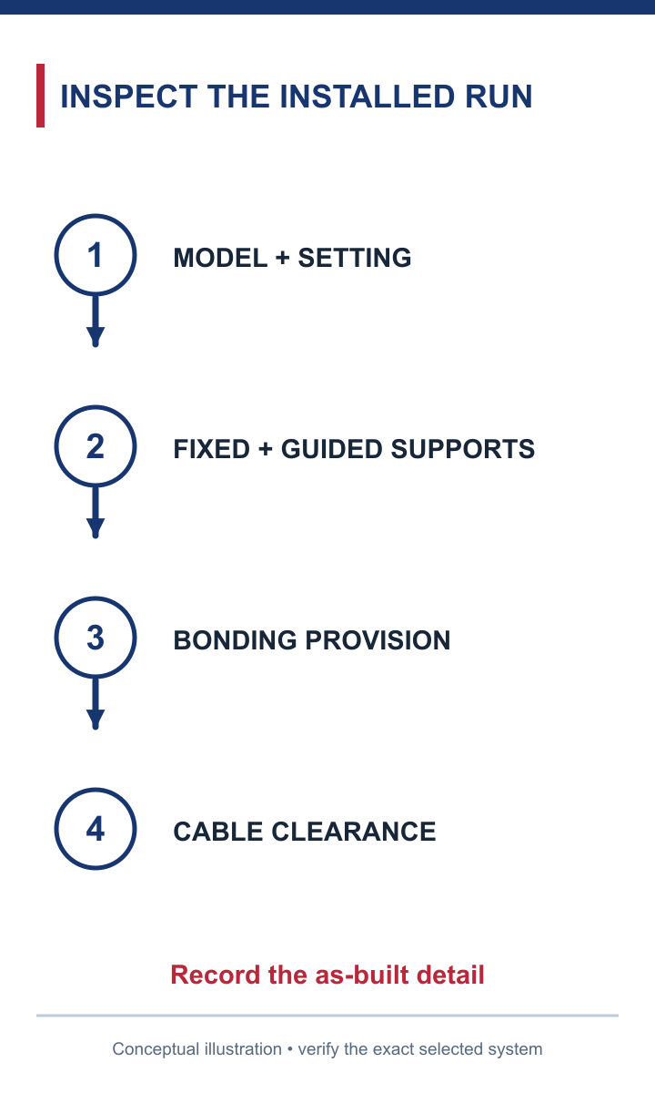
Conceptual process flow; verify the exact selected system.
The most damaging mistakes come from splitting a connected decision into isolated purchases. Do not choose a coupler without a movement calculation; do not set its gap without the installation temperature and exact product instruction; and do not approve the connection without checking fixed points, guides, cables and continuity. An ordinary splice is not an expansion detail, and a component that can move is not proof that the route has been laid out to let it move.
Before release, ask five practical questions. What movement is the joint intended to take? Which model and ladder series prove the required travel and fit? Where is the fixed reference, and where must the ladder slide? How do cables and bonding cross the moving location? What will the installer measure and record? If any answer is missing, resolve it in the project detail. A cable ladder expansion joint succeeds when its setting, restraints and connected services all support the same movement plan.