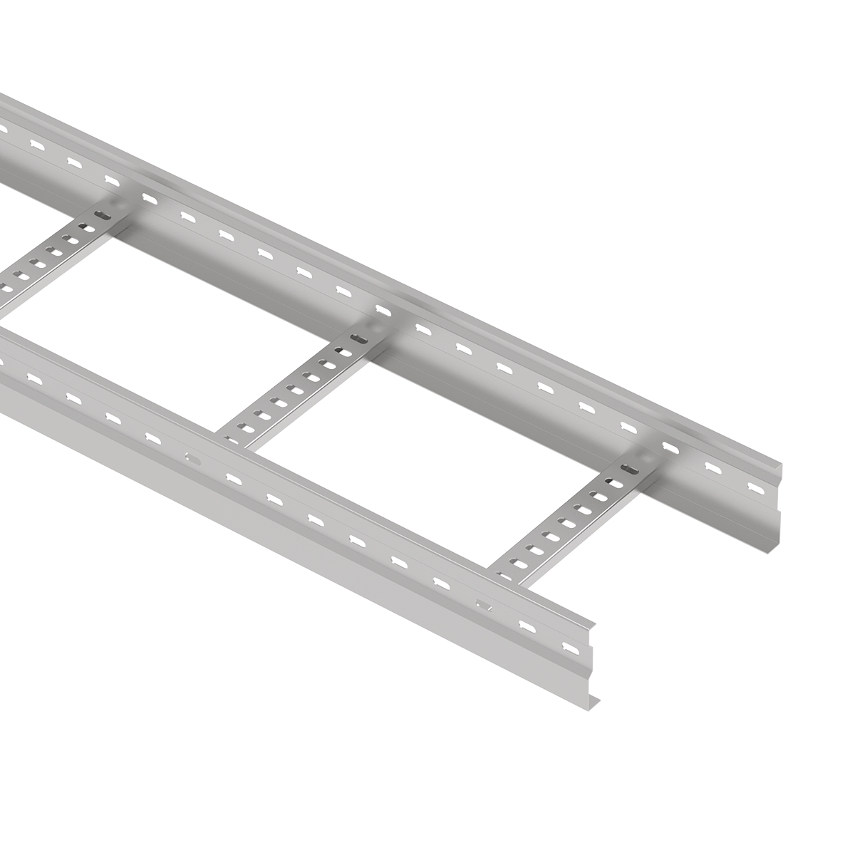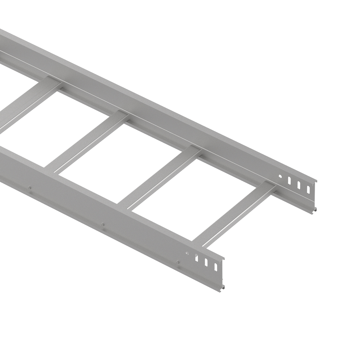
A reliable cable ladder installation depends on an approved route, suitable supports, matched connections and careful cable handling. These elements need to work together throughout the installation, from the first support bracket to the final inspection.
For electrical contractors, EPC teams and site engineers, the practical task is to translate project drawings and product data into a complete, inspectable system. This guide explains preparation, support requirements, nine installation steps, special site conditions and handover checks.
Use the approved project drawings, the selected manufacturer's installation instructions and locally applicable electrical requirements throughout the work. This article focuses on factory-assembled ladder sections; site-assembled products require their own assembly procedure.
Installation sequence: confirm the route and design → install supports → position ladder sections and fittings → complete expansion and bonding arrangements → lay and secure cables → inspect and hand over.
Review the latest approved layout, cable schedule and installation details before ordering components or marking supports. Confirm ladder width, side-rail height, section length, route elevations, fitting locations and interfaces with equipment.
The design should identify the cable load and any specified future allowance. Check how the manufacturer defines its published load rating, including whether ladder self-weight is included. Supports and anchors must be assessed for the loads they actually carry.
Use allowable working-load data for the selected configuration. A destructive test result alone is not an installation load rating.
Also confirm required product approvals and technical documentation for the specific model. Keep unresolved design questions on a query list; agree changes before they become site work.
For broader product selection, see ECTRAY's cable ladder selection guide.
Survey the route against actual site conditions. Identify clashes with ductwork, pipework, structural members, lighting and equipment. Check that installers can lift sections into position and reach connection points.
Allow the access required by the project for cable installation, inspection and future maintenance. Pay particular attention to congested corridors, service shafts and equipment rooms.
Confirm the specified material and finish against the exposure conditions. Indoor humidity, outdoor weather, coastal salts and chemical exposure create different selection requirements. Use the approved specification rather than assuming that every metal or coating suits every location.
Compare deliveries with the packing list and approved specification. Check dimensions, quantity, identification, finish and visible damage.
Separate incompatible components and quarantine items requiring supplier review. Confirm that splice plates, fittings, fasteners, clamps and bonding accessories match the selected system.
Store components so they remain identifiable and protected from damage and trapped moisture. Organize straight sections and fittings by installation area to simplify handling and reduce misplaced materials.
Prepare tools around the actual material, connection system and work method.
| Task | Typical Tools or Equipment |
|---|---|
| Route setting-out | Tape measure, marking tools and laser or spirit level |
| Support installation | Approved drilling equipment, sockets and spanners |
| Controlled tightening | Suitable torque wrench where a specified torque applies |
| Section preparation | Material-appropriate cutting tools, files and deburring tools |
| Electrical checks | Instruments suitable for the specified inspection and test procedure |
| Access and handling | Suitable lifting and access equipment, plus task-specific protective equipment |
A powered driver can assist installation, but final tightening must follow the connection manufacturer's procedure. Protect finished surfaces during handling, and treat the ladder as cable support equipment: it is not a walkway or access ladder.
A complete installation normally involves straight ladder sections, supports, connections and project-specific accessories.
Confirm availability of:
Distinguish required components from optional items. Covers, dividers and drop-out protection should serve the project design; their presence is not a substitute for correctly selected supports or cable restraints.
Wall brackets, trapeze hangers, steel-beam attachments and floor-mounted supports provide different ways to carry the system.
Check the load path through the ladder, bracket or cross-member, fixings and supporting structure. A correctly selected ladder does not resolve an undersized bracket or unsuitable anchor.
For suspended systems, check hanger and cross-member alignment. For wall or floor installations, verify bracket positioning and the supporting surface. Do not drill or modify structural members without the approval required by the project.
ECTRAY's cable support products provide a starting point for discussing mounting arrangements.
There is no single support spacing suitable for every cable ladder installation. Confirm the selected model's load-versus-span data and the support conditions used to establish it.
Check that the planned span is compatible with the cable load, ladder configuration, support system and project design. Reassess local changes, concentrated loads and special site conditions.
Keep three dimensions separate:
Record the approved span on the installation drawing. Clear identification is more useful than a general range presented without a product or loading condition.
Determine connection positions together with support locations. Follow the selected system's detail for ordinary splices, bends, branches, reducers and expansion connections.
| Location | What to Confirm |
|---|---|
| Straight splice | Permitted position relative to supports |
| Bend, tee or reducer | Support arrangement for that fitting |
| Expansion connection | Nearby supports, joint movement and fixed-point arrangement |
| Change in elevation | Ladder support and cable restraint requirements |
Assess the ladder's structural support and the cables' weight-bearing restraints separately. They perform different functions.
The vertical design should identify support positions, cable restraint locations and loads transferred through those components. Confirm additional requirements at transitions and terminations.
For vibration, seismic or other special conditions, use the approved project details. A shorter interval selected without design verification does not establish that the overall arrangement is suitable.
Transfer the approved route and elevations onto the site using a consistent reference. Mark straight runs, direction changes, equipment interfaces and support positions.
Check each area against other services before drilling. Resolve clashes while the route is still being set out.
Identify fittings and expansion locations at the same stage. Confirm that section lengths and intended splice positions work with the support layout. Record approved departures from the drawing so subsequent trades and inspectors use the same information.
Install brackets, hangers, cross-members and anchors using the specified components and installation procedure.
Verify the substrate, anchor type and required fixing details. Check alignment and elevation before placing ladder sections. Adjustments are easier while supports remain accessible.
Inspect the completed supports against the approved layout, including any special bracing or restraint. Record the fastening checks required by the project.
Before lifting sections, confirm that the supports are ready to receive the planned load and that the handling method will protect the ladder and surrounding equipment.
Confirm whether field cutting or drilling is permitted for the selected product. Measure the required length against the route, connection detail and remaining rung arrangement.
Use suitable cutting equipment and remove sharp edges and metal debris. Examine the prepared section before installation.
Apply the specified repair procedure wherever modification damages a protective finish. ZM, GI, HDG, powder-coated steel, stainless steel and aluminum require attention to their respective fabrication and surface requirements.
If the intended change affects connection holes, a welded rung or another structural feature, obtain an approved modification detail before proceeding.
Place factory-assembled sections on the supports, align the side rails and check the route elevation.
Install the matching splice plates and supplied or specified fasteners in the required orientation. Follow the product's tightening procedure and verify that the splice is in an approved location relative to the supports.
Use the prescribed attachment arrangement for each support position. Where the design requires sliding movement, preserve that function.
Confirm the electrical connection requirements for the splice. Mechanical assembly alone should not be treated as evidence that every bonding requirement has been met.
Install route fittings according to the approved layout and matching connection details. Check widths, side-rail heights, orientation and intended direction of travel.
Coordinate the fitting radius with the cable manufacturer's bending requirements. Verify cable entry and exit paths, especially where a horizontal run changes to a vertical route.
Complete the specified fitting supports before cable installation. Review branch points for congestion and access.
Use approved fittings or approved fabrication details for route changes. Field alterations should preserve the required mechanical support, cable protection and electrical connection arrangement.
Follow the expansion layout for long runs and locations requiring movement. Confirm the selected joint's permitted travel and the gap setting for the installation temperature and design temperature range.
Distinguish a support from a longitudinal fixed point. Supports carry the ladder; the arrangement of fixed points and guides controls where movement occurs.
Install each attachment for its intended function. Do not turn a sliding guide into a fixed clamp through incorrect tightening or positioning.
Complete any specified bonding arrangement across movement joints without obstructing their travel. Check the whole expansion segment, including nearby supports, before accepting the joint.
Complete grounding and bonding according to the project electrical design and applicable requirements.
Check connections between ladder sections, fittings and associated metalwork within the specified bonding scope. Install the designated terminals, conductors or jumpers where required.
Ordinary bolted joints, adjustable connections, expansion joints and finished surfaces may require different treatment. Follow the approved detail for each connection type.
Verify the required electrical continuity and protective connection arrangement. Record the specified inspection and test results, including acceptance criteria.
If the ladder is intended to serve as an equipment grounding conductor, confirm that the product and complete installation satisfy the applicable conditions for that use.
Inspect the route before introducing cables. Confirm that supports, connections, edge treatment and required bonding work are complete.
Plan the pull or laying operation around cable weight, bending limits and permissible pulling tension. Use suitable rollers and handling equipment where required, with attachment arrangements approved for the installation.
Arrange cables according to the project design, including circuit formation, segregation and thermal requirements. Avoid uncontrolled crossing, jacket damage and excessive tightening of restraints.
Select cable restraints for their actual duty. Weight-bearing support on vertical routes and restraint against short-circuit forces require verified arrangements. Preserve identification and access to cable terminations.
Complete covers, dividers, end closures and protective accessories required by the design. Install cable exit protection before feeding a cable across the relevant edge or opening.
Route-changing fittings should already be installed before cable laying. Finish remaining protective accessories in the planned sequence without disturbing cables or bonding connections.
Inspect the completed route against the approved drawings. Check attachment points, accessible fasteners, cable arrangement and the functioning of movement connections.
Remove debris, record outstanding items and close them before handover. Update the installation documents to reflect approved site changes.
Match materials, finishes and associated hardware to the approved exposure specification. Inspect surface damage after handling and installation, and complete the applicable repair work.
Select compatible fasteners and brackets. Where different metals meet, use the approved connection detail for the environment.
Where outdoor covers are specified, confirm their fixing arrangement and the loads transferred to the system. Remove trapped debris and check locations where water or contamination can collect.
Service-life expectations should be assessed from the actual material, exposure and maintenance conditions. Avoid assigning a fixed lifespan to every cable ladder system.
Establish expansion requirements from the ladder material, design metal temperatures, run length and joint movement capacity. A fixed interval applied to all projects does not account for these inputs.
Coordinate movement joints with structural movement requirements and fixed-point locations. Check that the installed guides allow the movement assumed in the design.
After cable installation, inspect the segment again: added accessories or restraints must not unintentionally prevent the intended ladder movement.
Use the approved vertical restraint arrangement to carry cable weight and protect equipment terminations.
Cleat selection and spacing should consider cable diameter, formation, axial load, fault forces and the supporting structure. Vertical loading or short-circuit forces can govern the required spacing.
Do not assume that a general cable tie has the verified capacity needed for weight-bearing or fault restraint. Use the specified restraints and installation procedure, including requirements at bends and terminations.
Coordinate wall and floor penetrations with the relevant structural and fire-protection details. Where a rated barrier is involved, follow the approved penetration system for the actual cable and opening arrangement.
Check weather sealing where required and provide cable protection at interfaces.
Maintain access to connections, movement joints and areas scheduled for inspection. Changes by other trades should not obstruct the agreed maintenance space or prevent future cable work.
The most useful corrective action is to compare the installed detail with its approved basis.
| Mistake | Corrective Action |
|---|---|
| Using one span for every ladder model | Confirm the selected product's load and support conditions |
| Confusing rung spacing with support span | Label both dimensions separately on drawings |
| Placing splices without checking the support detail | Verify the permitted connection position |
| Changing supports or fittings without review | Confirm the revised load path and document approval |
| Restricting an expansion segment | Check fixed points, guides and accessories together |
| Leaving modified edges unfinished | Deburr, clean and complete the required surface treatment |
| Using unsuitable cable restraints | Verify the duty and installation arrangement |
| Assuming bolted assembly proves bonding compliance | Complete the specified electrical checks |
| Adding cables without reassessment | Review loading, fill, thermal conditions and restraints |
Use this checklist with the project's inspection procedure. Enter the applicable drawing, product requirement or test criterion as the acceptance basis.
| Check Item | What to Verify | Status / Record |
|---|---|---|
| Route and elevation | Installation matches the approved layout | Record result |
| Product identification | Correct sections, finishes and accessories | Record result |
| Supports and anchors | Approved type, positions and installation details | Record result |
| Straight connections | Matching plates, permitted locations and fastening | Record result |
| Fittings | Correct orientation, radius and support arrangement | Record result |
| Prepared edges | No harmful burrs; specified repair completed | Record result |
| Expansion arrangement | Gap, fixed points, guides and movement clearance | Record result |
| Grounding and bonding | Specified connections and test records complete | Record result |
| Cable arrangement | Approved formation, segregation and restraint | Record result |
| Accessories and penetrations | Required protection and sealing complete | Record result |
| Handover documents | As-built drawings, changes and inspection records | Record result |
Close outstanding items and identify responsibility for corrective work. Keep the completed checklist with the installation records.
Set inspection frequency through the project maintenance plan and operating environment.
Examine sections, supports, fasteners, finishes, cable restraints and bonding connections. Look for damage, unexpected movement, contamination and signs of changed loading.
Check movement joints and penetrations, and investigate significant findings rather than simply retightening every connection. Repairs must preserve the designed function of guides and adjustable components.
Review cable additions before installation. Available physical space does not establish structural or electrical capacity.
Check the revised cable load, supports, anchors, permitted fill, circuit arrangement and thermal requirements. Confirm that added restraints, covers or connections are compatible with the existing system.
Record the approved change and inspect the modified area after completion.
Maintain a record of inspections, defects, corrective work and route changes. Include the relevant drawings, product identification and test results.
A clear history helps maintenance teams understand what was installed, what changed and which design assumptions remain applicable.
Confirm the approved route and support design, install supports, connect ladder sections and fittings, complete expansion and bonding arrangements, then lay and secure cables. Inspect the finished system and record approved changes. Factory-assembled and site-assembled ladders require their respective product instructions.
Use the selected model's allowable load-versus-span data and approved support design. Confirm the cable load and relevant support conditions. Ladder section length and rung spacing are different parameters and should not be substituted for the structural support span.
Locate joints according to the selected system's connection detail and approved support layout. Ordinary splices, fitting connections and expansion joints can have different requirements. Verify the complete arrangement rather than applying one distance to every joint.
Metal ladder systems require the protective connection arrangement specified by the applicable electrical rules and project design. Confirm which joints provide verified continuity and where separate bonding components are required. Product approval alone does not confirm that the installed connections are complete.
Assess thermal movement using the material, design metal temperatures, run length and permitted joint travel. The design should also address structural movement where relevant. Confirm joint positions, gap settings, fixed points and guides as a coordinated arrangement.
Only make modifications allowed by the selected product instructions and project design. Use appropriate tools, remove burrs and debris, and complete the required finish treatment. Changes affecting structural members or connection details require an approved procedure.
ECTRAY supplies steel cable ladder systems with fittings and support options for power, industrial and infrastructure applications.
For project planning, request the relevant dimensions, finish options, connection details and load information for the selected model. Confirm the scope of any required certification against that product and application.
Planning a cable ladder installation? Contact ECTRAY with your BOQ, routing drawings, cable load requirements, support arrangement and installation environment to discuss suitable sections, fittings and supply requirements.