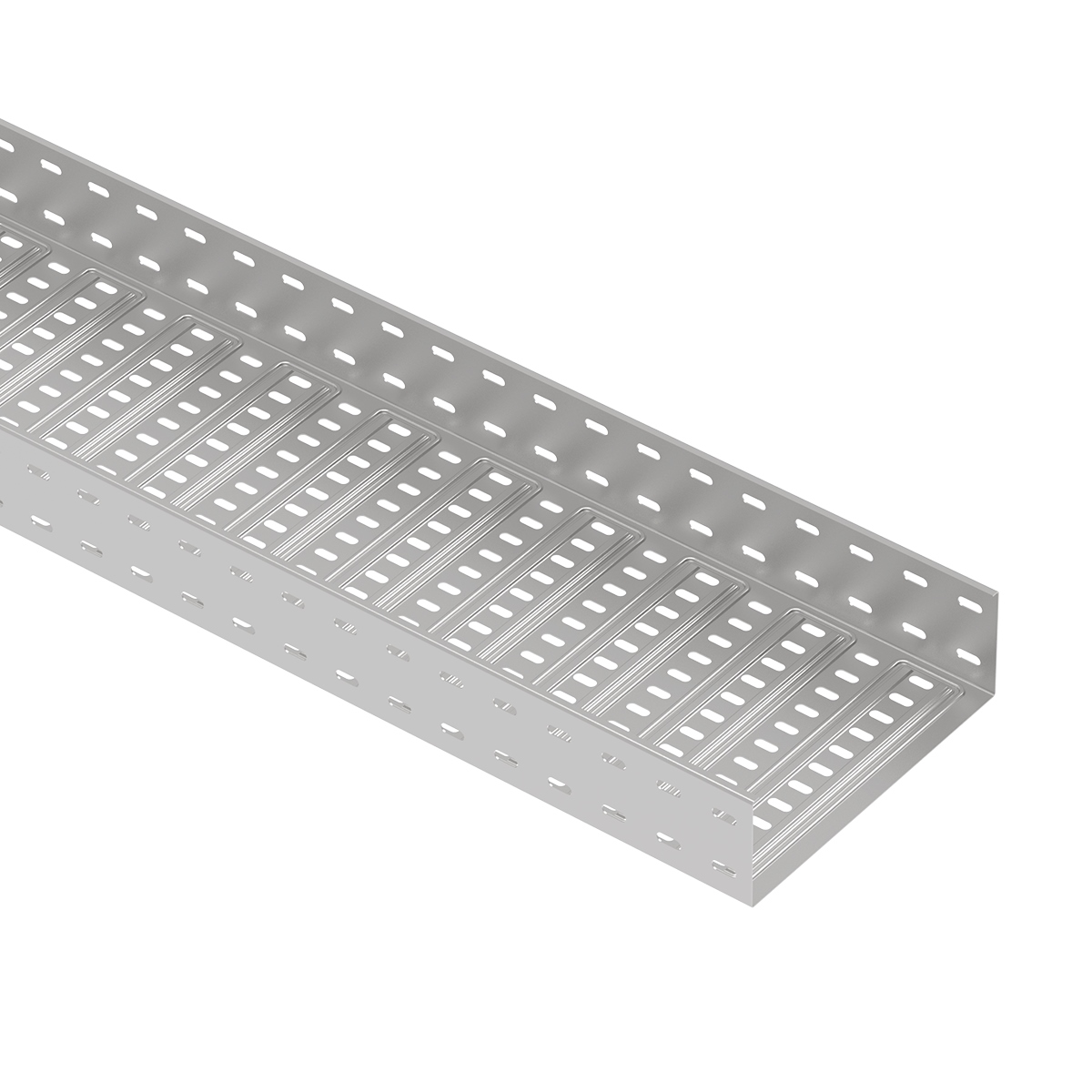
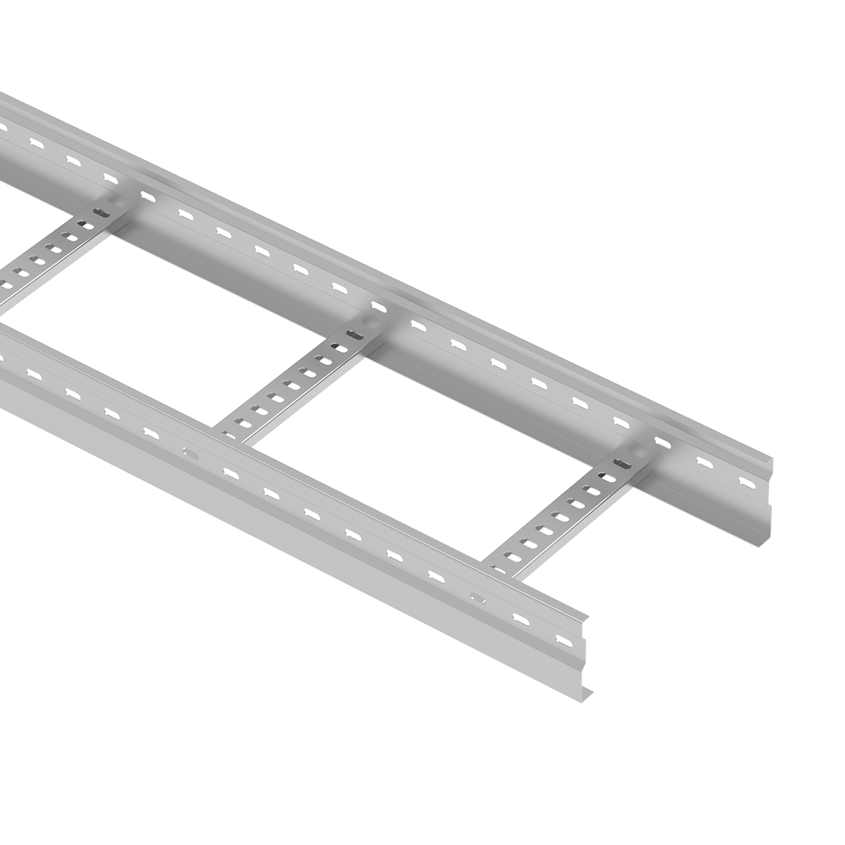
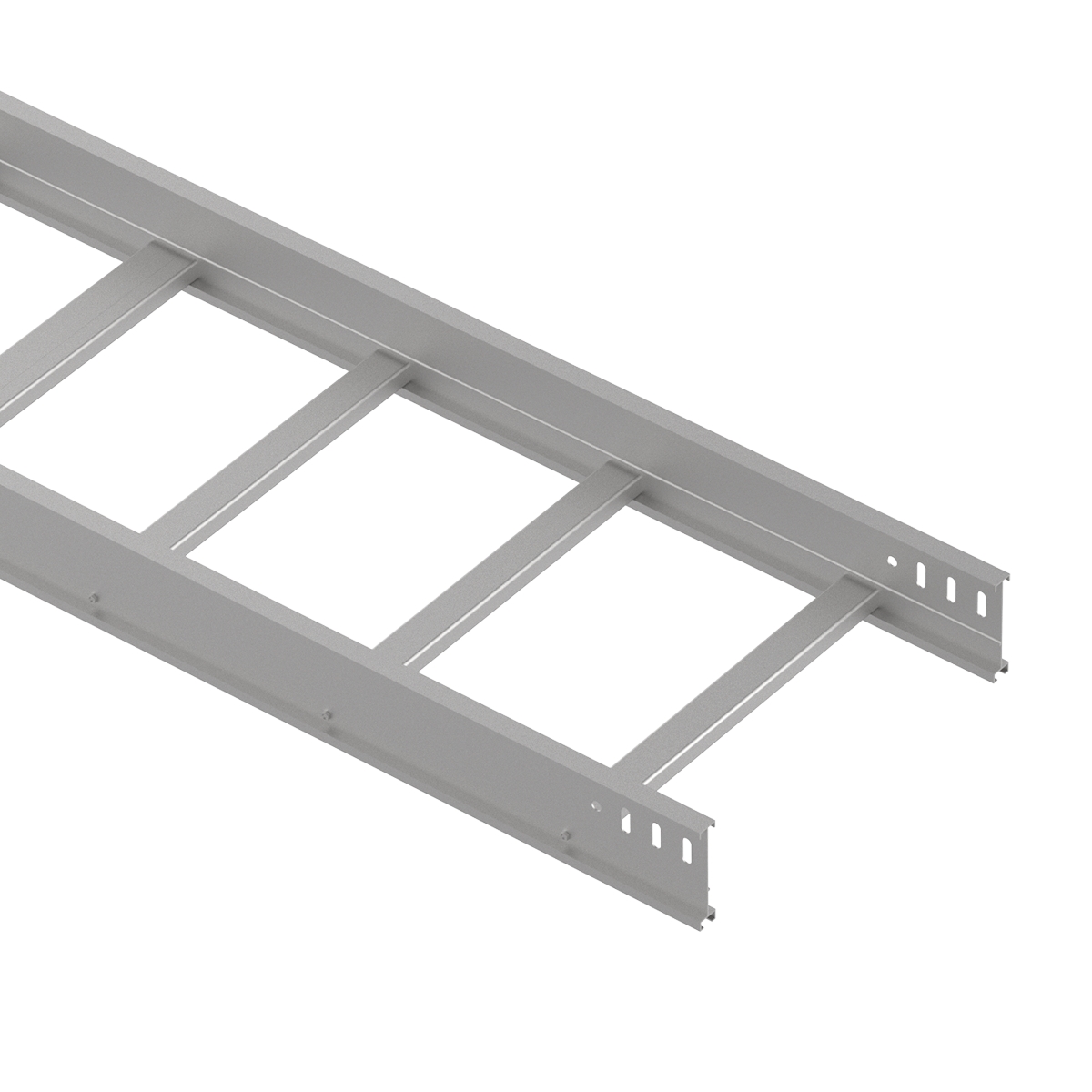
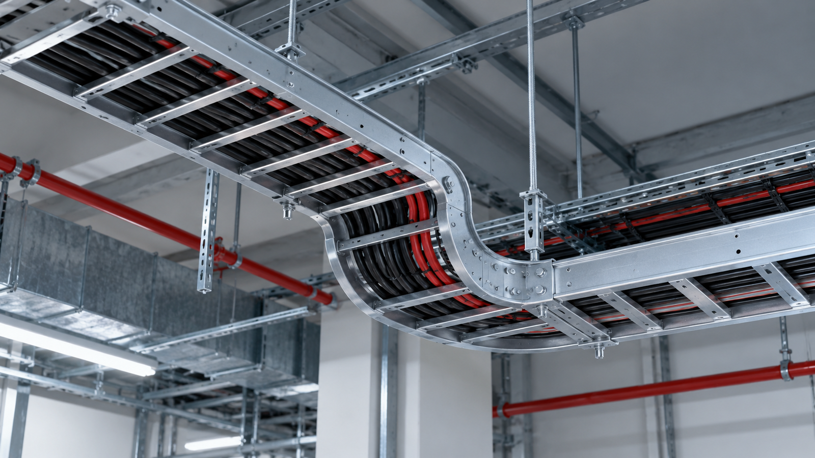
The perforated cable tray vs cable ladder decision starts with how the cables need to be supported. A perforated tray uses a formed base with openings, while a cable ladder supports cables on rungs between two longitudinal side rails.
That structural difference affects cable contact, access and routing. However, it does not establish a universal winner for load capacity, support span, corrosion resistance or cost.
A suitable system must meet the cable installation requirements and the project’s loading, environmental and maintenance conditions. In some projects, different route sections benefit from different support systems.
This guide compares the two options and explains what engineers, contractors and procurement teams should verify before making a selection.
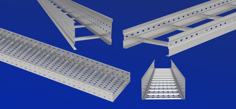
Use this table to identify the differences worth investigating. Final selection requires information for the specific products being compared.
| Comparison Point | Perforated Cable Tray | Cable Ladder |
|---|---|---|
| Basic structure | Formed sheet base with openings and sidewalls | Side rails connected by spaced rungs |
| Cable contact | Closely spaced support across the base | Support at rung positions |
| Small-cable support | Base may suit cables requiring frequent support | Confirm suitability for the specified rung spacing |
| Ventilation | Openings permit airflow where unobstructed | Large open areas around the cables |
| Cable entry and exit | Use suitable exits, fittings and edge protection | Open spaces between rungs provide routing opportunities |
| Load capacity | Configuration-specific | Configuration-specific |
| Support span | Verify using relevant performance data | Verify using relevant performance data |
| Environmental protection | Open construction; not a sealed enclosure | Open construction; not a sealed enclosure |
| Maintenance | Depends on cable arrangement, covers and access | Open underside can improve visibility and access |
| Total cost | Depends on the complete supplied and installed system | Depends on the complete supplied and installed system |
Both systems provide a pathway for suitable cables. Their main distinction is the structure supporting the cables along the route.
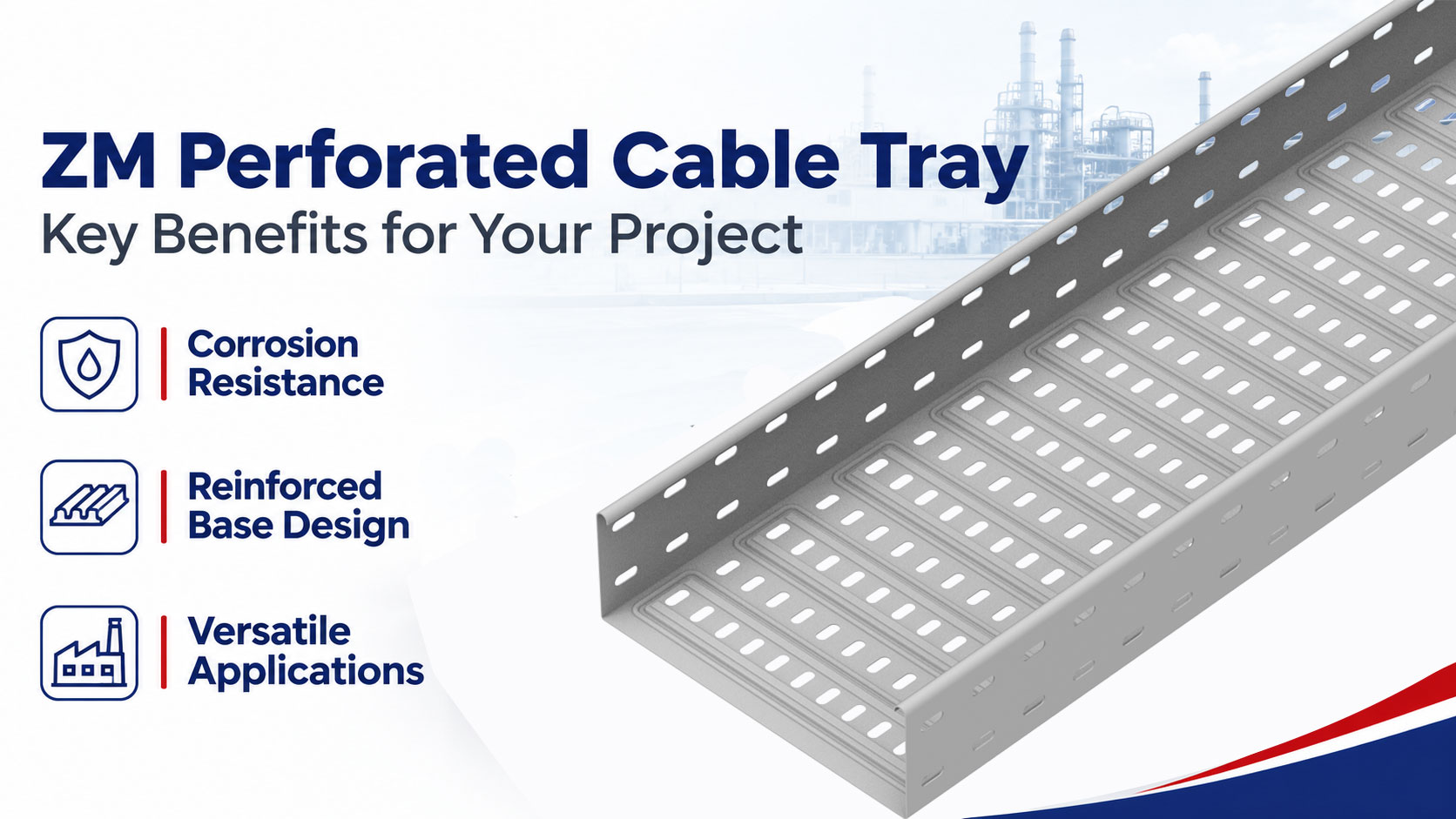
A perforated cable tray has a formed base with holes or slots and raised sidewalls. The remaining base material provides support between the openings.
It can suit cable arrangements that need more frequent contact points than a widely spaced rung system provides.
ECTRAY offers configurations without stamped bottom stiffening and with stamped bottom reinforcement. Their structural performance should be reviewed against the selected dimensions, thickness, material and support conditions.
A perforated tray is different from a solid-bottom tray. Its openings do not provide a sealed barrier against water, dust or spills.
A cable ladder consists of two side rails joined by transverse rungs. Cables rest on the rungs and are restrained where required by the design.
The open construction provides access around the cable route and can accommodate cable entry or exit between rungs, subject to bending and support requirements.
Cable ladders are commonly considered for industrial power routes and large cable installations. Their working load and permitted span still depend on the particular rail profile, rungs, connections and supporting arrangement.
A complete installation includes more than straight sections.
Both systems may need bends, risers, tees, crosses, reducers, splice plates, supports and fastening components. Covers, dividers, cable restraints and bonding parts are added where specified.
Check component compatibility within each system. Similar dimensions do not guarantee that fittings or splice plates are interchangeable.
Supports and anchors also require their own load assessment.
Cable characteristics should guide the comparison before considering appearance or unit price.
A perforated base provides closely spaced cable contact across the remaining sheet surface. A ladder supports cables at discrete rung positions.
The practical question is whether the cable can bridge the available gaps without exceeding its installation requirements.
Check the cable manufacturer’s guidance on support spacing, bending and restraint. A large cable is not automatically suitable for every rung spacing, and a small cable does not automatically require a perforated tray.
Small or flexible cables may need frequent support to control sag, bending or local contact pressure.
A perforated tray can be an option where its base and openings suit those requirements. Check hole edges, transitions and any bottom contours that contact the cables.
A cable ladder may also be suitable where rung spacing and approved accessories provide adequate support. Additional support should be specified only where needed.
Do not use a top cover as a substitute for a cable-supporting base.
Large power cables require coordinated mechanical and electrical assessment.
Compare cable weight, support intervals, fastening requirements, bend radius and installation forces. Cable grouping and electrical loading also affect the permitted arrangement.
Either support type may be appropriate when the specific configuration meets these requirements. Avoid selecting a ladder solely because the cables are heavy or rejecting a perforated tray solely because it has a sheet base.
Plan separation according to cable function and applicable requirements. Where necessary, use suitable dividers or separate routes.
Select restraints for their intended duty. Cable organization, vertical weight support and short-circuit restraint can require different components.
Check bend radius at fittings and equipment entries. Increasing straight-section width does not automatically resolve an unsuitable fitting radius.
Open construction influences the conditions around cables, but it does not replace a thermal or environmental assessment.
A ladder has large open areas, while a perforated tray provides openings through its base and sometimes its sidewalls.
Air movement also depends on cable coverage, grouping, ambient conditions, nearby surfaces and covers.
Neither product automatically guarantees acceptable cable temperature or ampacity. Use the relevant cable installation method and correction requirements when assessing thermal performance.
A ladder provides open spaces through which water and debris may pass. A perforated tray provides drainage openings, which can become obstructed by cables or contaminants.
Both can accumulate material on cables, joints and structural surfaces.
Assess the actual exposure, mounting orientation and cleaning access. Avoid describing perforated tray as dust control or cable ladder as maintenance-free.
Covers may reduce exposure from above, depending on their construction. They also change access, thermal conditions and structural loading.
Outdoor covers need suitable retention for applicable wind conditions. Their weight must be included on the appropriate load basis.
A covered tray or ladder should not be described as watertight, dust-tight or electromagnetically shielded without supporting evidence for the complete assembly.
For perforated cable tray vs cable ladder comparisons, load and span should be reviewed together.
Capacity depends on material properties, section geometry, thickness, connections, support conditions and load distribution.
For perforated trays, the base and sidewall profiles require consideration. For ladders, the rails, rungs and rung connections all matter.
The weakest relevant component or performance criterion can govern the selection.
Product names such as “heavy duty” should therefore be supported by configuration-specific information.
Use equivalent conditions when comparing two products.
| Information | What to Confirm |
|---|---|
| Product configuration | Width, height, thickness and structural details |
| Material | Grade and relevant properties |
| Support span | Distance between adjacent supports |
| Load basis | Uniform, concentrated or combined loading |
| Self-weight | Whether included in the published value |
| Connections | Splice type and location |
| Deflection | Applicable criteria and results |
| Evidence | Test report, calculation or other identified basis |
Where performance is calculated rather than tested, state that distinction clearly.
Do not convert a maximum destructive load or linear buckling factor directly into an allowable cable load.
Formed edges, rail profiles and reinforcement can change stiffness and local stability.
ECTRAY’s stamped bottom profiles are intended to improve local base behavior. That does not independently establish a fixed increase in overall working load or permitted span.
Likewise, a deep ladder rail does not establish capacity without checking rungs, connections and support conditions.
Compare the offered configurations rather than assuming that visible reinforcement or additional thickness proves equivalent performance.
Review service deflection alongside strength and stability.
Splices, fitting connections, brackets, rods and anchors must suit the proposed arrangement. A straight section’s performance does not automatically cover every branch or transition.
Cable installation forces and other applicable project loads may also need assessment.
Neither system should be used as a personnel walkway unless specifically designed and approved for that purpose.
Practical access depends on both the product structure and where it is installed.
Open spaces between ladder rungs can provide convenient cable exit points. Suitable bend-radius control and restraint may still be needed.
Perforated tray routes can use designed exits, drop-outs and fittings. Field cutting should follow permitted methods, with appropriate edge treatment and surface protection.
Neither system should rely on cables bending across sharp edges or unsupported transitions.
Both products use system-specific fittings and joints.
Confirm component availability, assembly requirements, fastening procedures and support positions. There is no universal rule that perforated tray always needs more fasteners or that ladder always needs fewer supports.
Compare actual route drawings and installation instructions when estimating work.
A ladder’s open underside can improve visibility and access around cables. A perforated tray provides a base beneath them.
However, covers, cable density, overhead clearance and neighboring services may have a greater effect on maintenance access than the product type.
Plan how technicians will reach connections and replace cables without damaging adjacent circuits.
Reserve capacity should address both usable space and cable weight.
Define likely additions where possible. An arbitrary percentage of empty space does not establish structural or electrical capacity.
Before adding cables, review grouping, loading, support conditions, fittings and access. Keep route records current after approved changes.
Corrosion resistance should be evaluated separately from the choice between tray and ladder.
Steel systems may be available with different protective finishes.
Select against actual exposure, fabrication details and maintenance requirements. Avoid universal claims that one finish is best for every outdoor or coastal project.
Stainless steel grade selection depends on the actual moisture, salt, chemicals, temperature and cleaning conditions.
Aluminum alloy may be evaluated where system weight is important. Alloy, geometry, connections and exposure still require review.
Availability can differ by product range. Material substitution should include a structural and compatibility assessment.
Review fasteners, supports and connection parts alongside the main sections.
Dissimilar-metal contact, coatings and moisture can affect corrosion behavior. Any isolation measures must also remain compatible with structural fixing and required bonding.
Do not select fastener material solely because it matches the tray or ladder. Confirm grade, coating and assembly requirements.
Industry labels provide context, but the actual route conditions determine the choice.
Evaluate ladders where open access, cable restraint and large power cable routes are priorities.
Evaluate perforated trays where closely spaced base support suits the cable arrangement.
Both require suitable load, span, material and installation evidence.
Consider usable space, cable separation, fitting dimensions and maintenance clearance.
Perforated trays can suit routes needing a supporting base, while ladder systems may suit cables compatible with rung support.
Neither automatically provides electromagnetic shielding or fire resistance.
Bridges, tunnels, airports and rail facilities can involve movement, vibration, exposure and restricted maintenance access.
Compare structural attachments, route transitions and the evidence required by the project.
Different sections within one facility may justify different support systems.
Assess roof fixing, drainage, cable exposure, wind actions and maintenance access.
Product type alone does not establish reduced uplift, better corrosion resistance or outdoor cable suitability.
Coordinate the support system with the roof or equipment design.
Review the cable manufacturer’s support and bending requirements, along with separation and physical protection.
Perforated bases may suit cables requiring frequent support. Ladders may also be suitable when rung spacing and compatible accessories meet the requirements.
Cable organization and electrical segregation should follow the actual design.
Compare systems that meet the same project requirements before comparing prices.
Material quantity, grade, profile, thickness, length and finish influence cost.
Neither product is always lighter or less expensive. Use actual supplied weights and quotations rather than a general assumption.
Count the supports, fittings, connections and restraints required by each proposed arrangement.
Consider handling, access, field cutting and fastening work. A lower price per meter may be offset by additional components or installation effort.
Assess expected inspection, cleaning and modification work for the actual environment.
Do not assume a fixed maintenance frequency based only on tray type. Exposure, material, installation quality and accessibility influence the work required.
A useful comparison includes:
| Cost Item | Scope to Compare |
|---|---|
| Straight sections | Equivalent functional requirements |
| Fittings and joints | Complete route quantities |
| Supports and anchors | Approved support arrangements |
| Restraints and covers | Required accessories |
| Documentation | Specified drawings, reports and approvals |
| Installation | Handling, fixing and modification work |
| Delivery | Packaging, transport and schedule |
| Maintenance | Realistic access and exposure assumptions |
Compare the actual configurations at the required span. The product category does not establish a universal capacity ranking.
Perforated trays can be configured for different loads. Suitability depends on the documented performance and cable requirements.
Cable grouping, electrical loading, ambient conditions and covers remain relevant to both systems.
Compare all required components and installation conditions. An incomplete quotation is not a reliable basis for selection.
List cable quantities, outside diameters, weights, bend radii and restraint needs.
Confirm that the proposed support arrangement is suitable for each cable group.
Multiply each cable quantity by its weight per meter, then add the results.
Define future additions and account for accessories and other applicable loads on a consistent basis.
Compare candidate configurations against the proposed span, loading and deflection requirements.
Identify whether the supporting evidence is tested, calculated or otherwise qualified. Missing information should be resolved before assigning an allowable load.
Check corrosion exposure, physical protection, maintenance access and space through fittings.
Do not select one system solely because the project is described as industrial, outdoor or commercial.
Confirm fittings, splices, supports, restraints and any covers or dividers.
Review drawings, installation instructions, material specifications and relevant performance documents for the offered configuration.
Yes. Different route sections may have different cable support, access or structural requirements.
A project may use ladder for one distribution route and perforated tray for a branch where closer cable support is needed.
Specify the reason for each choice and identify the transition locations on the drawings.
A mixed system should result from route requirements rather than an assumption that one type belongs in every main run and the other in every branch.
Use compatible transition details that preserve cable support, bend radius and access.
Assess the transition itself, including its connections and supports. Applying the shorter of two nominal support spans does not automatically validate the transition assembly.
Provide electrical continuity or bonding as required by the design. Confirm movement and material compatibility where systems meet.
ECTRAY manufactures perforated cable trays, cable ladders, supports and related accessories.
Review the perforated cable tray range and steel cable ladder options when preparing your specification.
For a useful technical discussion, provide:
Comparing perforated cable tray vs cable ladder for a project? Send ECTRAY your route and cable requirements to discuss suitable configurations and request a quotation.
Perforated tray supports cables on a formed base with openings. Cable ladder supports them on spaced rungs between side rails. This affects cable contact, access and routing.
Yes, where the selected configuration meets the cable load, support span, deflection and installation requirements. Use relevant performance evidence rather than the product name.
They may be suitable if rung spacing and the cable support arrangement meet the cable manufacturer’s requirements. Approved supplementary support may be needed.
Compare specific products at the required load and span. Ladders are often considered for such routes, but their suitability still requires configuration-specific evidence.
A ladder generally has a more open structure. Actual thermal performance also depends on cable arrangement, loading, ambient conditions, nearby surfaces and covers.
No. Compare the complete system, including supports, fittings, restraints, installation, delivery and documentation.
Yes, when materials, finishes, cables, accessories and fixing arrangements suit the actual exposure and project loads.
Product type alone does not establish fire performance. Firestop and circuit-integrity requirements must be assessed using the relevant approved assemblies and project criteria.
Not automatically. Electromagnetic performance depends on the complete design, including openings, joints, covers, bonding and cable arrangements. Do not treat a tray or divider as verified shielding without supporting evidence.
No direct equivalence can be assumed. Compare the complete configurations under the same cable, load, span and installation requirements.