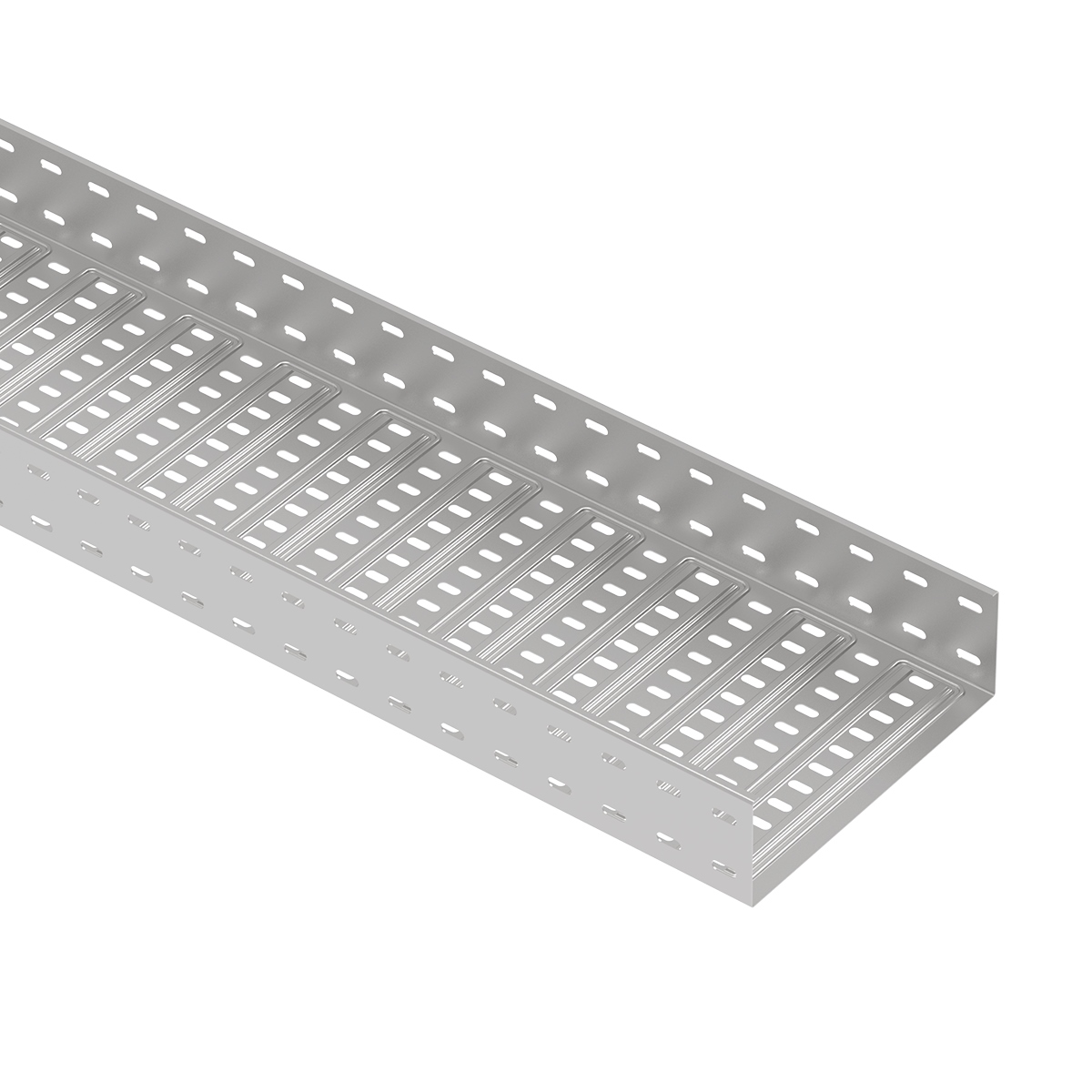
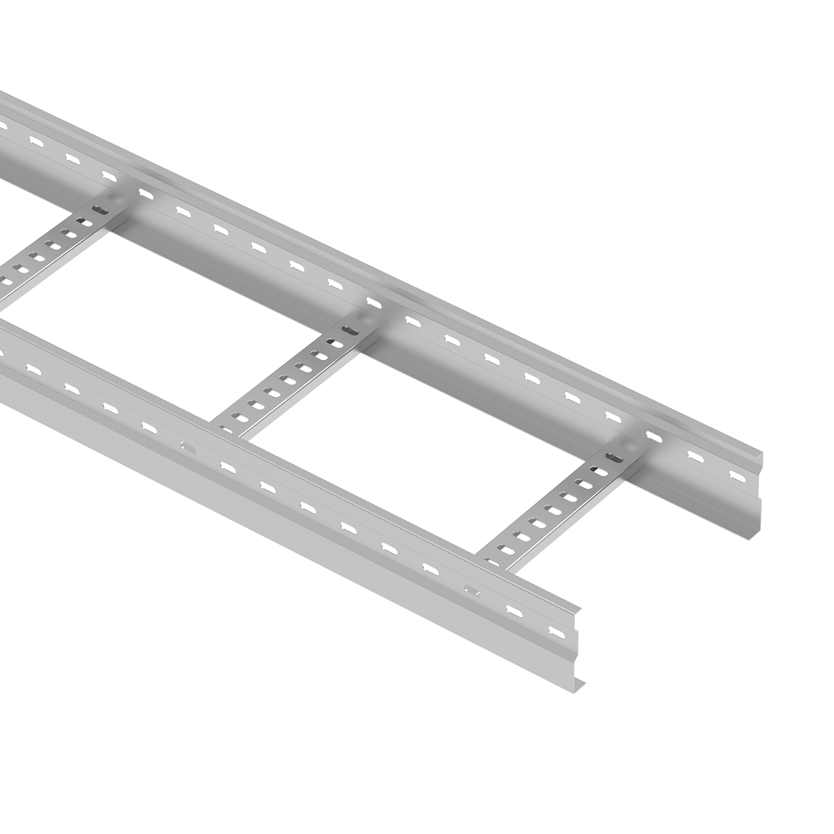
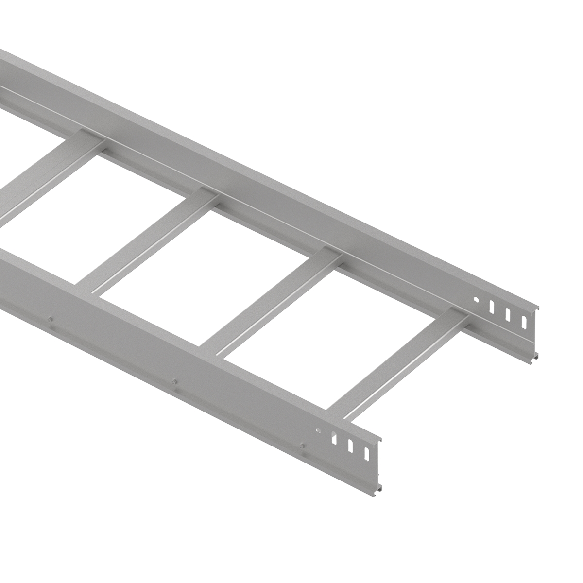
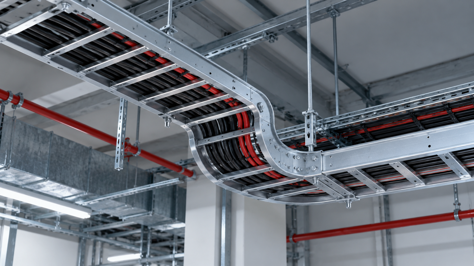
For a “bonding jumper cable tray” search, the practical answer begins with the joint: a cable tray bonding jumper is a conductive connection used where the installed tray system needs a separate path across a joint. It is not a part to add automatically at every splice. Properly installed standard rigid metallic splice plates may already provide the electrical continuity the route needs, while an adjustable, expansion or otherwise discontinuous joint may require a dedicated connection. The decision belongs to the exact tray system, joint and electrical design.
The useful first question is not “what length of jumper should I buy?” It is “what conductive path does this installed joint provide?” Trace the route through straight sections, fittings, splice plates and any movement joints. Then check the manufacturer's instructions and the project grounding design. A catalogue jumper with an attractive price or a familiar wire size cannot answer those questions on its own.
This guide separates the joint decision from accessory selection. It explains why the Cable Tray Institute cautions against blanket jumpers at standard rigid splices, why Eaton gives conditional guidance for its systems, and what information a buyer should obtain before asking a supplier for a compatible accessory. It does not prescribe a universal conductor size or claim that a product from one tray family fits another.
Begin with the installed metalwork, not the loose jumper. A tray run may have straight sections, horizontal and vertical fittings, branch pieces and splices. Each connection has a physical joint and an electrical continuity question. A drawing that shows the geometry but not the joint type can hide a break in the intended path.
The Cable Tray Institute's grounding and inspection material focuses on continuity between sections and the connection of the tray system to the grounding arrangement. That is different from assuming every bolt makes a satisfactory electrical bond. Surface finish, hardware, joint design and installation condition matter. The responsible team should identify the manufacturer's approved splice method and inspect the real installation against it.

Trace the installed conductive path before selecting an accessory.
For each joint, write down the tray family, material, fitting type, splice hardware and any movement allowance. Note whether there is a standard bolted rigid plate, an adjustable connection, an expansion piece or a deliberate discontinuity. These categories guide the next question; they are not a substitute for the adopted electrical rules or the maker's instructions. The deliverable is a traceable bonding path that an installer and reviewer can follow.
A common overstatement is that a cable tray needs a bonding jumper at every joint. The Cable Tray Institute says properly installed standard one-piece metallic bolted side-rail splice plates on aluminum or steel trays can maintain electrical continuity without an added parallel jumper. That conclusion concerns that specific standard rigid-splice arrangement, not every possible connector or installation.
Check the actual plate and rail contact, the specified fasteners and the manufacturer's installation instructions before relying on it. A loose, altered or incompatible splice is not rescued by quoting a general statement about standard plates. Equally, buying extra jumpers does not excuse a deficient primary joint or an unreviewed grounding design.
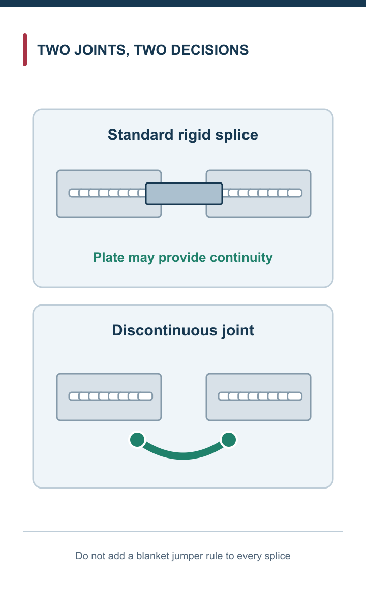
A properly installed standard rigid splice is different from a discontinuous joint.
The Institute describes historical fault-current testing of standard splice assemblies. Those results help explain its position, but they are not a universal certification for another brand, finish or joint. The Institute page also contains older code references and apparent typographical errors; this article deliberately does not repeat those numbers as current requirements. Use the current adopted code and the exact product's published documentation for the project decision.
Some connections are not standard rigid splices. An expansion joint has to accommodate movement. An adjustable or articulated fitting may use a different contact arrangement. A section can also be electrically discontinuous because of a design detail, a nonstandard plate or the way it has been installed. Those are the places to investigate a separate bonding connection rather than simply count all splices.
Eaton's public answer says bonding jumpers are required on both rails when the tray is not continuously grounded or when splice plates that are not UL listed are used. That is useful manufacturer-specific guidance, but it should not be converted into an unqualified rule for every cable tray. The supplier's system detail, listing and installation manual remain essential. An expansion or adjustable joint can have its own prescribed jumper and hardware arrangement.

Movement joints need manufacturer- and project-specific continuity review.
Document each exception on the route drawing. Show the fitting or joint designation, the intended bond path and who approved the detail. If a field change replaces a standard plate with another connector, reopen the review; an earlier “no jumper” decision may no longer apply. This is particularly important where a drawing is copied to another area with a different tray material or fitting family.
Bonding tray sections together is not the whole equipment-grounding design. The installed system also has to be connected and used in accordance with the applicable electrical requirements. Whether a metal tray is permitted to serve as an equipment grounding conductor, or is merely bonded while a separate conductor provides the equipment-grounding path, depends on the system design and adopted rules.
Do not treat a short jumper across one joint as proof that the route can carry the required fault current or satisfy all grounding obligations. Conversely, do not infer that a separate equipment-grounding conductor eliminates every continuity requirement for the metalwork. These are related but distinct decisions. The project electrical designer must establish the required path, termination method and inspection criteria.

A local joint bond does not determine the whole equipment-grounding design.
An effective drawing makes those roles visible. It shows where the tray begins and ends, how the sections and fittings are joined, where the bonding or grounding connections occur and what happens at discontinuities. An installer can then verify a particular connection rather than guess from an accessory's presence. This also helps a later inspector distinguish an intentionally unjumpered standard splice from a missed movement-joint detail.
A compatible jumper is a system accessory, not just a length of green wire. Confirm the tray manufacturer's family and model, the joint type, rail or fitting geometry, conductor or braid type, lug arrangement, hole pattern, fasteners and the applicable installation instructions. A jumper can be electrically plausible yet physically unsuitable for the available connection points.
The Legrand Itray listing is an example of a named accessory for its ladder-tray system. SitePro1 and other catalogue pages show jumpers and straps with particular lengths, lug patterns and stud sizes. Those examples demonstrate that products differ; they do not establish interchangeability with an ECTRAY tray or another manufacturer. Search results also mix cable runway straps and rack components into cable-tray queries.

Confirm accessory compatibility with the exact tray system and joint.
Ask for the exact part drawing and the tray or fitting it is intended to connect. Check whether the part is supplied with the proper terminations and hardware, and whether the installation procedure requires surface preparation or another connection treatment. If a proposed substitute changes any of those elements, obtain a documented approval rather than silently replacing the specified accessory.
The conductor or braid size, length and termination need an engineering basis. A fixed number lifted from an online product listing is not a safe universal selection rule. The project may have a particular adopted code edition, grounding configuration, fault-duty calculation, tray system and manufacturer detail that control the answer.
NEMA's installation guidance points designers and installers back to the applicable electrical requirements when a jumper is needed. Use the current project documents and exact maker instructions to determine the connection points and hardware. The cable should be long enough for the joint's intended movement or geometry without being strained, but an unnecessarily long lead is not a substitute for a reviewed design. The termination must fit the specified lug and contact surface.

Project rules and electrical duty govern size and termination.
Record the selected jumper designation, conductor size, material, lug and fastener detail, and the rule or approved drawing behind them. If the source document is an older errata sheet, verify that the project actually uses the relevant edition before copying its wording. Have the responsible electrical reviewer sign off on the chosen assembly and inspection method.
A search for “bonding jumper cable tray” presents product cards as well as technical explanations. Distributor listings can be useful for checking available lug patterns and dimensions, but they are not a code interpretation. Some visible items are for cable runway, equipment racks or a particular ladder-tray family. Their titles can look close to the query while their connection purpose differs.
Use the product page to answer narrow questions: what is sold, what are its terminals, what is its nominal length, and which family does the maker specify? Use manufacturer installation documents and the adopted electrical design to answer whether it belongs at the proposed joint. If the listing omits compatibility or installation evidence, treat that as a missing input, not as permission to assume a fit.

Catalogue dimensions do not prove system compatibility.
The same distinction applies to broad technical articles. The Cable Tray Institute's standard-splice argument addresses a defined joint type; Eaton's answer addresses its own conditions. Neither tells you the lug pattern of an ECTRAY fitting you have not identified. A robust specification joins the technical reason for a bond to a product that demonstrably fits the actual system.
Inspection should confirm the installed path rather than just count green wires. Compare the route with the approved drawings: straight sections, splices, expansion or adjustable connections, fittings and any separate jumpers. Check that the specified hardware is present, secured and accessible, and that the contact and finish condition matches the approved procedure. Look for corrosion, loose fasteners, damaged lugs, strained conductors or a joint modified after the design review.
The Cable Tray Institute's inspection guidance gives a useful system-level perspective: continuity depends on the installed assembly, not merely an isolated component. A visual check can identify obvious defects, but the project may also prescribe testing and documentation. The responsible electrical team should define those acceptance steps and interpret any measurements under the applicable project criteria.

Inspect the as-built assembly, not only the drawing.
Record the as-built connection and any deviations. If a jumper was added, note why the joint needed it and which approved detail it follows. If a standard rigid splice is unjumpered, record the basis for treating its installed plates as the continuity path. That record makes later repairs and extensions safer than a rule remembered only as “we usually add a jumper.”
Use this checklist before approving a cable tray bonding-jumper schedule:

The decision is conditional on the actual system and joint.
| Check | Why it matters | Evidence to obtain |
|---|---|---|
| Tray and fitting family | Accessories are system-specific | Exact model and installed route drawing |
| Joint type | Standard rigid, adjustable, expansion and discontinuous joints differ | Splice and fitting detail |
| Intended electrical path | Continuity and EGC duties are not identical | Approved grounding design |
| Jumper need | A standard rigid plate may already provide continuity | Manufacturer instruction and joint review |
| Accessory fit | Lug, rail, hole pattern and hardware must match | Product drawing and installation sheet |
| Size and termination | Fault duty and adopted rules govern | Electrical calculation or approved schedule |
| Verification | A design is not an as-built inspection | Test/inspection record and deviations |
Keep the checklist with the specific project rather than turning it into a generic purchasing rule. A replacement tray, different splice plate or added expansion joint can change the answer. Before ordering, ask the design owner to mark every unresolved row. A supplier can then quote a defined assembly rather than a guessed jumper size.
ECTRAY's public product range establishes that it supplies cable tray systems, but the available range page does not publish one universally compatible bonding jumper for all its trays and joints. That boundary matters. It would be misleading to recommend a jumper solely because a buyer searches for an ECTRAY cable tray and a generic jumper on the same day.
For an ECTRAY route, begin with the selected tray family and the exact joint or fitting requiring review. Ask which splice plates and fasteners belong to that system and whether the proposed assembly relies on a standard rigid metallic splice for continuity. Where a separate jumper is indicated by the project design, request a named compatible accessory or a documented approved detail, not an informal promise that a catalogue item should fit.
ECTRAY can respond to a concrete enquiry with technical drawings and product-selection guidance. The qualified project team still has to decide the electrical requirements and approve the installed connection. That division of responsibility keeps the commercial discussion useful without presenting a public product listing as a compliance certificate.
Send the tray schedule, route drawing and applicable grounding or bonding detail with the enquiry. Identify every joint in question: standard rigid splice, adjustable fitting, expansion section or other discontinuity. Give the tray material and finish, section width and side-rail geometry, and any specified splice hardware. If a particular accessory is proposed, include its drawing rather than just its name.
Ask for the part number and drawing of any recommended jumper, including conductor or braid, length, terminations, hole spacing, fasteners and its intended tray or fitting family. Request the maker's installation and inspection instructions. Where the project has a specified fault duty, bonding schedule or adopted code edition, supply those to the electrical reviewer; a supplier should not infer them from a photograph.
The returned proposal should identify assumptions and exceptions. If ECTRAY cannot establish compatibility from the provided information, the appropriate next step is to request the missing drawing or clarify the joint—not to substitute a visually similar strap. A precise enquiry gives procurement, engineering and installation teams the same connection to review.
For anyone using “bonding jumper cable tray” as a product search, the answer is conditional: a cable tray bonding jumper belongs where the actual system and joint need a separate conductive connection. Properly installed standard rigid metallic splice plates can provide continuity without a parallel jumper; adjustable, expansion or discontinuous connections need their own review. No generic product listing settles that decision for every tray.
Map the bonding path, identify the exact joint, consult the tray manufacturer's instructions and have the responsible electrical designer confirm the applicable requirements. Then select a physically compatible accessory with a documented size, termination and installation detail. Inspect the finished assembly against that record.
For an ECTRAY project, send the tray and joint drawings plus the bonding schedule before asking for a jumper recommendation. That approach is slower than choosing a search-result part number, but it prevents a small accessory from becoming an unsupported assumption in a safety-critical system.