Cable ladder load capacity must be evaluated at the support span proposed for the installation. The permitted load depends on the ladder's material, side-rail profile, thickness, rung construction, connections, and the conditions covered by its technical documentation.
For an EPC contractor, electrical designer, or procurement team, selection starts with the cable schedule and route drawing. These establish the cable arrangement, mass per meter, available support positions, and any additional loads. The next step is to match those requirements to a verified ladder and support configuration.
This guide explains how to calculate cable loading, compare support spans, read a cable ladder load capacity chart, and specify ECTRAY cable ladder sizes for power, industrial, and infrastructure projects.
Cable ladder load capacity is the permitted load for a specified ladder configuration at a stated support span and under defined conditions. The rating should identify the product construction, loading method, support arrangement, and any installation restrictions.
For a horizontal route, cable weight is commonly assessed as a uniformly distributed load along the ladder. Equipment attached at one position, or a localized cable load, can create a concentrated load requiring a separate check.
| Term | Meaning | Typical unit |
|---|---|---|
| Uniformly distributed load, or UDL | Load distributed along the ladder length | N/m or kN/m; sometimes expressed as equivalent mass in kg/m |
| Concentrated load | Load applied at a particular location | N or kN; sometimes expressed as equivalent mass in kg |
| Safe working load, or SWL | Declared permitted working load under stated conditions | As specified in the product documentation |
| Destructive or ultimate load | Load reached at failure in a defined test | As recorded in the test report |
| Support span | Distance between the centerlines of adjacent supports | mm or m |
| Deflection | Displacement of a side rail or rung under load | mm |
A destructive test result and a working-load rating describe different conditions. Request the declared working load and its assessment basis when reviewing a test report. A published rating should also be checked for the load types and installation conditions it covers.
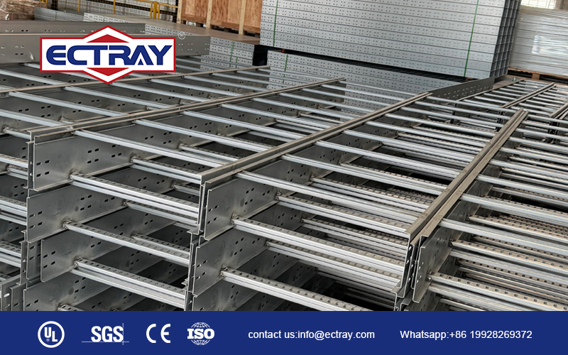
The ECTRAY dimensions covered by this guide are:
| Parameter | Dimensions |
|---|---|
| Tray Width | 200–1000 mm |
| Side Rail Height | 100 mm, 150 mm, 200 mm |
| Straight Section Length | 2 m or 3 m |
| Length in Millimeters | 2000 mm or 3000 mm |
Choose width using the cable schedule and proposed cable arrangement. Consider cable outside diameters, circuit separation, maintenance access, and planned additions. Verify usable internal dimensions on the drawing, including any divider positions.
Calculate the mass per meter of the proposed cable arrangement at the same stage. The selected width must accommodate the cables, while the complete ladder construction must meet their mechanical loading requirement. Electrical fill, spacing, and thermal requirements also need to be checked for the project.
Side-rail height influences the rail cross-section, but capacity also depends on its profile, thickness, and material. A deeper rail can improve bending performance when the other structural details are suitably designed; the actual rating must come from the matching product documentation.
Avoid assigning a load category from height alone. Review the 100, 150, and 200 mm options against the required load and span. Also confirm usable cable depth from the rung position and drawing dimensions.
Straight section length is the length of the supplied piece. Support span is the installed distance between supports. Both dimensions must be coordinated with the route and connection arrangement.
A 3 m section may need intermediate support, depending on its loading and verified construction. Selecting a 2 m section also does not automatically establish a 2 m permitted span. Confirm support positions and splice locations using the applicable load and installation information.
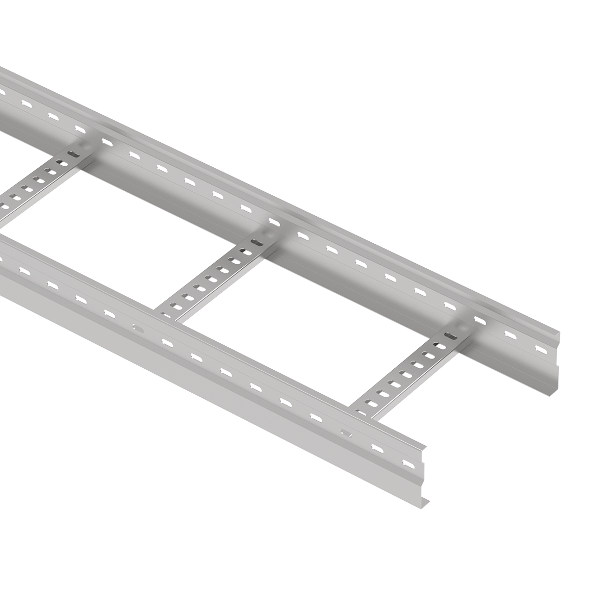
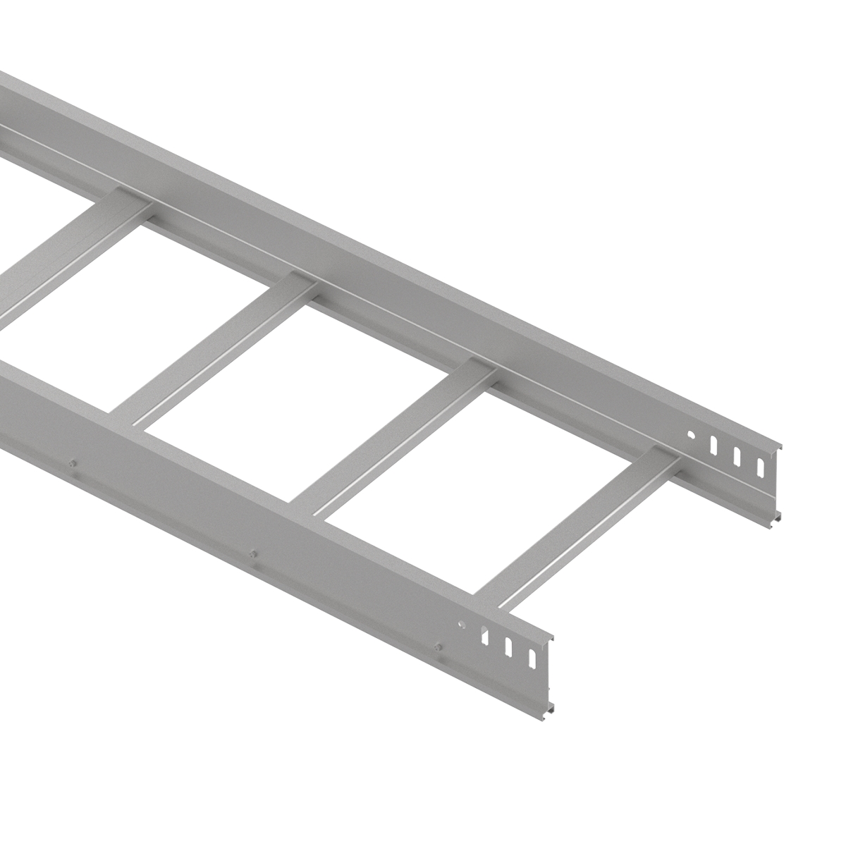
The side rails carry longitudinal bending between supports. Profile geometry, section depth, flanges, thickness, and material properties influence strength and stiffness. These details should be identified on the proposed product drawing.
A specification such as “150 mm high steel cable ladder” leaves the rail profile and thickness unresolved. Request the complete configuration and its corresponding load data, particularly where the project requires heavy cable loading or fewer support positions.
Rungs transfer cable loads across the ladder width to the side rails. Their profile, spacing, and attachment method determine how they carry local loads. Wider ladders require the rung design to be verified for the increased transverse span.
Closer rung spacing can provide more frequent cable support and change the load carried by each rung. It does not establish the longitudinal rating of the complete ladder. Check cable support requirements and any cleat, cable drop, or equipment attachment loads separately.
Compare materials using the documented performance of the complete product at the same span and under equivalent conditions. Steel, stainless steel, and aluminum configurations can differ in geometry and stiffness as well as material properties.
HDG, ZM, and powder coating describe surface protection rather than a load class. Select protection for the actual environment and specify the substrate material and grade separately. Match the load documentation to the supplied construction, including relevant connections and supports.
Splice plates and fasteners transfer forces between sections. Their design, bolt arrangement, and joint position must match the conditions covered by the technical documentation. Installation torque should follow the applicable instructions.
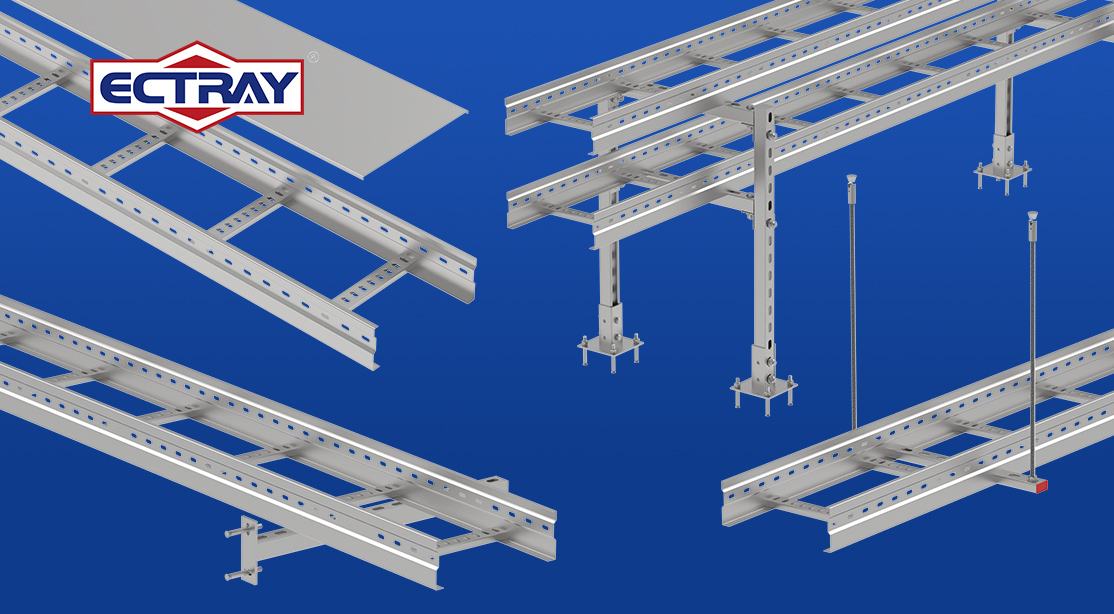
Supports then transfer loads into the building or other structure. Check brackets, channels, hanger rods, anchors, and the supporting structure for the forces and moments they receive. The ladder rating covers only the conditions stated for that ladder configuration.
Calculate loading for each route segment using the cables present in that segment. Use the cable manufacturer's mass per meter for the exact cable type, including armor and sheath construction where applicable.
The following calculation is an illustrative method. It does not represent a tested ECTRAY load rating.
For each cable group:
Cable group mass per route meter = number of cables × mass per meter of one cable.
Add the group values to obtain the cable mass per meter of that route segment.
| Cable group | Number of cables | Mass of each cable | Combined mass per route meter |
|---|---|---|---|
| Power cables | 10 | 2.40 kg/m | 24.00 kg/m |
| Secondary power cables | 8 | 1.10 kg/m | 8.80 kg/m |
| Control cables | 12 | 0.35 kg/m | 4.20 kg/m |
| Total installed cable mass | — | — | 37.00 kg/m |
This route segment therefore carries 37.00 kg of cable mass per meter. Its total route mass can also be calculated for estimating overall weight, but the load chart comparison needs a consistent per-meter value and loading arrangement.
Add the expected mass of planned circuits where their cable specifications are known. If a percentage allowance is used for preliminary planning, record that assumption and its basis.
For this example, assume a 20% allowance for additional cables:
Future cable allowance = 37.00 × 20% = 7.40 kg/m.
Cable mass including the allowance = 37.00 + 7.40 = 44.40 kg/m.
The 20% value is an example planning assumption. Future cable space and future cable weight should both be considered; an empty area in the ladder does not establish the remaining permitted mechanical load.
Record cover and accessory weights using the applicable product data. For this example, assume covers and accessories add a distributed mass of 3.60 kg/m:
Superimposed distributed mass = 44.40 + 3.60 = 48.00 kg/m.
Keep localized loads separately identified. Equipment mounted on one rung or at one position needs its weight, attachment method, and location assessed. Averaging that equipment mass over the full route can hide the local demand.
Confirm how the manufacturer's load table treats ladder self-weight. The ladder's own weight must be accounted for structurally, but it may already be included in the assessment underlying the published working-load rating.
For this example, assume the ladder weighs 6.00 kg/m:
Distributed mass of ladder and contents = 48.00 + 6.00 = 54.00 kg/m.
This value is relevant when establishing loads transferred to the supports. Include support-component weights and other applicable loads in the support and anchorage assessment. Keep the catalog comparison consistent with the manufacturer's self-weight convention to avoid double counting.
Use consistent units when comparing the loading requirement with the product chart. Using standard gravity:
Load in kN/m = mass in kg/m × 9.80665 ÷ 1000.
| Example loading basis | Mass per meter | Equivalent vertical force per meter |
|---|---|---|
| Cables, future allowance, covers, and accessories | 48.00 kg/m | Approximately 0.471 kN/m |
| The same loads plus assumed ladder self-weight | 54.00 kg/m | Approximately 0.530 kN/m |
These are calculated loading requirements. To select a ladder, obtain its permitted load at the intended span and compare using the same load definition. Assess concentrated, environmental, and installation loads using the relevant project conditions.
For an unchanged ladder carrying the same distributed load, increasing support span generally increases bending demand and deflection. A rating at one span therefore needs to be reviewed before changing the support spacing.
An ideal simply supported beam illustrates why span matters. Under a constant uniformly distributed load, maximum bending moment is proportional to the span squared. Elastic deflection is proportional to the span to the fourth power when the beam stiffness remains unchanged.
For that simplified model, increasing span from 2 m to 3 m produces:
These ratios explain the sensitivity to span. They are not a calculation of ECTRAY rated capacity. Actual ladder performance must account for the product construction, connections, support conditions, and applicable assessment method.
Review strength and deflection as separate selection checks. Where the project specifies a serviceability limit, obtain the corresponding deflection information at the proposed loading and span. Confirm whether the data describes a single-span or continuous installation.
A cable ladder load capacity chart should connect a declared load to an identified product and support arrangement. Before reading a value, confirm that the chart applies to the supplied configuration.
| Item to verify | Information required |
|---|---|
| Product | Model, drawing reference, and revision |
| Construction | Width, side-rail height, profile, thickness, rung design, and rung spacing |
| Material | Substrate and material grade |
| Support span | Distance covered by the declared rating |
| Load definition | UDL, concentrated load, working load, test load, or destructive load |
| Units | kg/m, N/m, kN/m, or other declared units |
| Test arrangement | Installation orientation and single-span or multi-span setup |
| Connections | Joint positions, splice plates, and fasteners |
| Deflection | Available results and the applicable acceptance criterion |
| Self-weight | How ladder weight is treated in the declared value |
Read the chart by identifying the model, locating the intended span, and checking the permitted load at that span. Then verify deflection information and all installation restrictions.
For the example calculation, an enquiry could request performance data for a 600 mm wide ladder with 150 mm side rails at a proposed 2 m span, carrying 48 kg/m of superimposed distributed mass. The rail thickness and other structural details would need to be confirmed during selection. This enquiry does not establish that the proposed size is adequate.
If the intended span is absent from the chart, request an approved assessment. Use any interpolation only under the manufacturer's documented method, and keep the assessed configuration unchanged.
Review the route drawing alongside the cable schedule. Mark potential support positions, changes of direction or elevation, cable drops, access areas, and building obstructions. Identify the structure that will receive the support loads.
Measure the proposed distances between supports and record any constrained locations. These distances become inputs for selecting the ladder construction and support system. The feasibility of an attachment point must also be checked for the resulting loads.
Where the layout permits different support arrangements, request corresponding performance information for each candidate span. For example, an enquiry might compare 1.5 m, 2 m, and 3 m spacings. These are example comparison points rather than universal ECTRAY recommendations.
Compare the full installation, including ladder construction, supports, connections, and installation work. A longer verified span can reduce support quantity while increasing the demand on the ladder and remaining supports. Use documented performance to establish which options meet the project requirements.
Coordinate bends, tees, crosses, reducers, risers, and expansion joints with the applicable support details. Fitting geometry and connected routes can change how loads enter the supports.
Check joint positions against the conditions covered by the ladder documentation. Follow the specified connection and fitting support arrangements. A general instruction to place every splice directly at a support does not describe all tested systems or all joint types.
Assess brackets, channels, hanger rods, fasteners, anchors, and the supporting structure for the applicable forces and moments. Where one support carries multiple ladder tiers, include their combined loading and arrangement.
A ladder UDL in kN/m and a bracket rating in kN describe different quantities. Establish the actual support reactions before comparing them with component capacities. Anchorage selection also depends on the substrate, fixing arrangement, and installation conditions.
Record additional project actions, such as wind, snow, ice, seismic effects, vibration, and loads from approved attached equipment, where applicable. Assess the relevant directions and combinations rather than treating every action as a vertical cable UDL.
Cable pulling and temporary installation equipment can introduce local forces requiring their own check. Plan personnel access with suitable access equipment or a purpose-designed walkway. A cable ladder's working-load rating does not by itself authorize pedestrian use.
Technical documentation should show how the declared performance was established. IEC 61537 specifies requirements and tests for cable tray and cable ladder systems. Its 2023 edition revised safe-working-load procedures and included tests for support devices and additional installation orientations.
NEMA metal cable tray requirements are also referenced in project and supplier documentation, including documents referring to NEMA VE 1. Confirm the exact standard designation and edition required by the project and recorded in the applicable report.
Different assessment methods have different conditions and acceptance criteria. Check the actual loading arrangement, connection positions, deflection criteria, and working-load basis when comparing results.
A useful technical submission identifies the model and construction, support span, installation orientation, loading method, declared working load, available deflection results, and installation limitations. If destructive-test data is supplied, keep it separately identified from the permitted working load.
Verify any certification against its stated product scope. A general certification reference cannot establish the permitted load for an unspecified ladder configuration or span.
Determine the cable arrangement and its mass per meter together. Width establishes the required cable space, while the verified ladder construction must meet the mechanical load at the proposed span. Both checks are needed before ordering.
A supplied 2 m or 3 m section still needs a suitable support arrangement. Confirm span and connection positions using the matching technical documentation. Any site change to support spacing should trigger a review of the affected route.
Confirm that load data matches the supplied model, material, rail profile, thickness, width, rung arrangement, and connections. Retain the approved drawing and rating with the purchase specification so substitutions can be assessed consistently.
Record equipment loads and heavily loaded route segments at their actual positions. Assess local rungs, connections, and supports as required. A whole-route average can obscure the demand at a concentrated load or cable branch.
Resolve support and anchorage details during design. Identify building constraints early so the specified span can be achieved. Coordinate ladder selection with the support system rather than deciding support positions only after the ladder arrives.
Review additions against the approved cable schedule, available cable space, and permitted load. Update the route loading assessment where cables or attached equipment change. Keep the relevant drawings and technical data available for maintenance teams.
The permitted load depends on the exact ladder construction, support span, and assessed installation conditions. Request the matching manufacturer's working-load data, including its load definition and restrictions, before selecting a product.
Multiply the number of cables in each group by the mass per meter of one cable, then add the results for the route segment. Include planned additions and applicable accessories, confirm the treatment of self-weight, and assess localized loads separately.
Use a span supported by the selected product's documented load and deflection performance. The route, joints, fittings, support hardware, anchorage, and site loads also influence the final arrangement. There is no single spacing suitable for every ladder.
No. The 3 m dimension describes the supplied section length. The permitted support span must be confirmed for the product and loading. Intermediate supports may be required.
Height alone does not establish capacity. Profile geometry, thickness, material, rungs, and connections also affect performance. Compare verified product values at the same span and under equivalent conditions.
Check the chart notes or ask the manufacturer. Self-weight conventions vary between published load statements. Ladder weight must be accounted for in the structural assessment, and the catalog comparison should follow the stated convention.
No. A destructive load records failure in a defined test. Safe working load is a separately established permitted value under stated conditions. Ask for both the working-load declaration and its assessment basis when reviewing destructive-test results.
This guide covers tray widths of 200–1000 mm, side-rail heights of 100, 150, and 200 mm, and straight section lengths of 2 or 3 m. Confirm thickness, rung construction, and load performance for the selected configuration.
Prepare your enquiry with the cable schedule, BOQ, route drawing, required dimensions, proposed support spans, material and finish requirements, and any additional project loads.
ECTRAY can review these inputs to discuss a cable ladder and support configuration for your project. Request the technical documentation applicable to the proposed model as part of the review.
Explore the ECTRAY steel cable ladder range and send your BOQ, specifications, or project details for technical review and quotation.