Proper cable ladder support design is essential for maintaining structural stability, controlling deflection, and transferring cable loads to the supporting structure.
A cable ladder does not work independently. Its performance depends on the ladder construction, installed cable load, support type, support span, fittings, connection details, and the structure to which the supports are attached.
Support spacing that is too large can increase structural demand and deflection, while unnecessary supports can increase material and installation requirements. The correct design therefore requires a balance between structural performance and project conditions.
This guide explains the main types of cable ladder support systems, how support spacing is determined, where supports should be positioned, and the key installation considerations for industrial, power, and infrastructure projects.
A cable ladder support system is the structural assembly used to support and secure cable ladder sections along a cable route.
Its primary function is to transfer the combined weight of the cable ladder, installed cables, fittings, and applicable additional loads to walls, ceilings, beams, floors, or structural steel.
Typical cable ladder support components include:
The support system should be considered together with the cable ladder rather than selected only after the ladder size has been determined.
A useful design principle is:
Cable Ladder + Cable Load + Support System = Complete Structural System
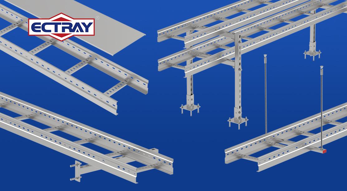
Different cable routes and building structures require different support configurations. The appropriate type depends on ladder width, cable load, installation height, available mounting structure, access requirements, and environmental conditions.
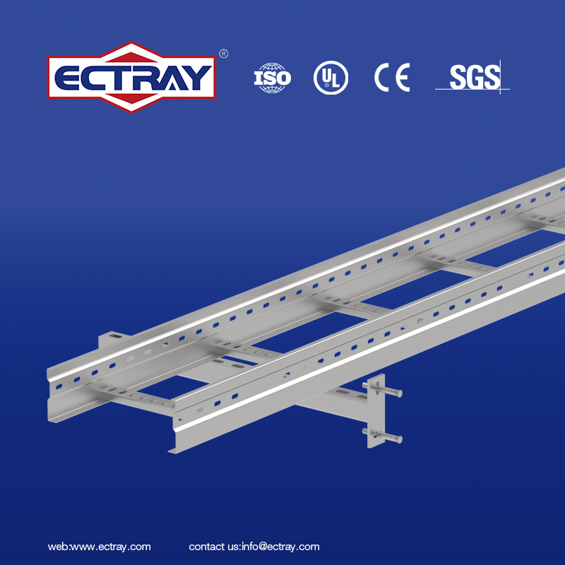
Wall-mounted brackets support the cable ladder directly from a wall or vertical structural surface.
They are commonly used where cable routes run parallel to walls and where overhead suspension is unnecessary or impractical.
Important selection factors include:
Longer cantilever distances generally place greater structural demand on the bracket and its connection to the wall.
For project design, the wall bracket, anchor system, and cable ladder should therefore be considered as one structural assembly.
Cantilever support arms project horizontally from a wall, column, or supporting frame.
They are widely used in industrial installations because they keep the space beneath the cable ladder relatively clear and provide convenient access to installed cables.
The required support arm capacity depends on:
Increasing the projection of the arm increases the moment applied to the support connection, so support arm dimensions should not be selected from cable ladder width alone.
Trapeze supports usually consist of two threaded rods connected by a horizontal support channel beneath the cable ladder.
This arrangement provides support from both sides and is commonly used for overhead cable routes.
Trapeze systems are suitable for:
The spacing between trapeze supports should be determined from the cable load, ladder construction, support configuration, and verified load-span information rather than from a single fixed distance.
Strut-channel systems provide a modular method of supporting cable ladders.
Channels can be combined with threaded rods, brackets, spring nuts, clamps, and other fittings to create adjustable support assemblies.
This type of system is particularly useful where installation height or cable route position may require adjustment on site.
Typical advantages include:
However, the capacity of the strut channel, fasteners, brackets, rods, and anchors must all be checked against the required load.
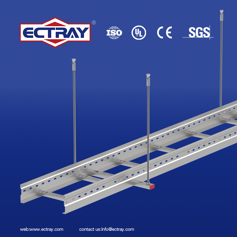
Hanging supports suspend cable ladders from ceilings, beams, or structural steel.
They may use threaded rods, beam clamps, channels, brackets, or other structural hardware depending on the building structure.
Hanging systems are commonly used for elevated cable routes where floor and wall space must remain clear.
Support design should consider:
The supporting building structure must also be capable of carrying the imposed load.
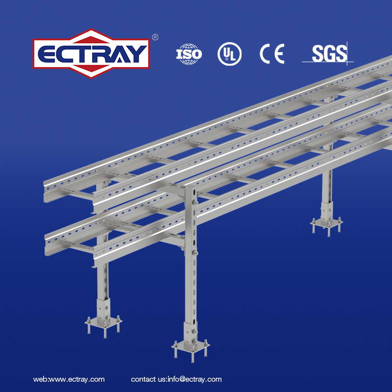
Floor-mounted or ground supports are useful where cable ladders run close to floors, rooftops, equipment areas, or other locations where ceiling suspension is not practical.
Support frames may use:
These systems can be particularly useful for heavy-duty cable routes and equipment-area installations.
The final spacing should still be determined from ladder load/span performance and the complete support design rather than applying one standard distance to every project.
Cable ladder support spacing, also called support span, is the center-to-center distance between adjacent structural supports.
As the support span increases, the bending demand on the cable ladder generally increases.
Shorter spans provide more frequent load transfer to the supporting structure, while longer spans place greater structural demand on the ladder side rails, connections, and support system.
Support spacing therefore affects:
NEMA VE 1 addresses construction, testing, and performance requirements for metal cable tray systems, while NEMA VE 2 provides installation guidance.
There is no single universal support spacing that applies to every cable ladder system.
General industry guidance sometimes uses approximately 1.5–3.0 m for cable tray straight sections, while another recent engineering reference gives approximately 2–3 m for ladder trays. Both sources also indicate that actual spacing must be confirmed from system design and manufacturer information rather than treated as a universal standard.
A practical design approach is:
| Installation Condition | Support Spacing Approach |
| Standard cable ladder | Confirm with manufacturer load/span data |
| Higher cable load | Shorter span or higher structural capacity may be required |
| Heavy-duty cable ladder | Project-specific load/span verification |
| Long-span installation | Structural verification required |
| Outdoor installation | Include applicable environmental loads |
| Bends, tees and crosses | Local support should be reviewed separately |
Important: General spacing ranges are design references only. They should not be treated as the allowable span of a specific cable ladder product.
The final support span should be based on the selected ladder configuration, cable load, verified manufacturer data, project specification, and applicable engineering requirements.
Several factors work together when determining the correct support spacing.
Cable load is one of the most important design inputs.
The total load should include the cables expected during normal operation and any future cable capacity included in the project design.
Higher cable loads increase structural demand. Depending on the selected cable ladder, this may require:
It is therefore more accurate to evaluate load and span together rather than assume that heavy cables always require one particular spacing.
Cable ladder width affects the system because wider ladders can accommodate larger cable quantities.
However, width alone does not determine support spacing.
Two cable ladders with the same width may have very different structural capacities because of differences in:
The actual installed load and verified structural performance are more important than width by itself.
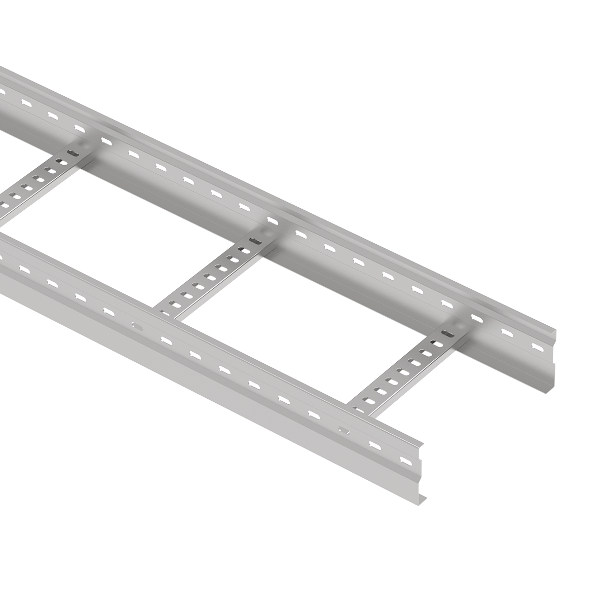
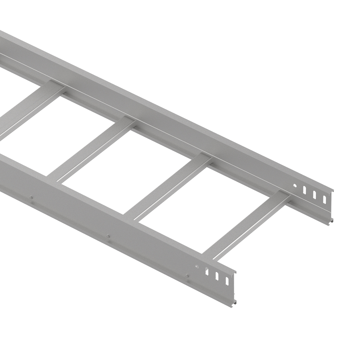
The side rails carry a significant portion of the longitudinal structural load in a ladder-type cable tray.
Side-rail height, profile shape, material, and thickness all influence stiffness and structural performance.
A deeper or reinforced side-rail profile may provide greater structural capacity, but this does not automatically mean that any taller side rail can use a longer support span.
The complete ladder configuration must still be verified.
Steel, stainless steel, aluminum, and other cable ladder materials have different mechanical properties.
Material thickness also affects structural performance.
However, support spacing should not be selected based only on statements such as:
“Steel can always span farther than aluminum.”
Actual allowable span depends on the specific ladder profile, material grade, thickness, manufacturing design, loading condition, and verified load/span performance.
Rungs provide transverse support for installed cables and form part of the complete ladder structure.
Important factors include:
Rung design should therefore be considered together with the side rails and complete ladder structure.
Deflection is the vertical displacement of the cable ladder between supports under load.
Excessive deflection may affect:
Allowable deflection should be evaluated according to project requirements, manufacturer data, and the applicable structural criteria rather than applying one universal deflection ratio to all cable ladder systems.
The surrounding environment may introduce additional design requirements.
Depending on the project, engineers may need to consider:
Outdoor and industrial installations may therefore require different support arrangements from a similar cable ladder installed indoors.
The cable ladder is only one part of the load path.
The supporting system may include:
Cable Ladder → Clamp → Bracket → Channel/Rod → Anchor → Building Structure
Every component in this path must be capable of carrying the required design load.
A strong concrete wall or steel beam does not automatically allow a longer cable ladder span. The ladder itself, the support hardware, the connections, and the structural attachment must all be suitable.
Cable ladder load capacity cannot be evaluated independently from support span.
As the distance between supports increases, bending demand on the ladder side rails increases. The same cable ladder configuration may therefore have different allowable loading conditions at different spans.
A simple way to understand the relationship is:
| Cable Load | Support Span | Relative Structural Demand |
| Lower | Shorter | Lower |
| Higher | Shorter | Moderate |
| Lower | Longer | Moderate |
| Higher | Longer | Highest |
The key principle is:
Higher Cable Load + Longer Support Span = Greater Structural Requirement
Manufacturer load/span data should therefore be reviewed before the final support spacing is selected.
Cable Tray Institute guidance also notes that manufacturers should make maximum allowable support information available for each loading and material configuration.
Support location is just as important as the overall spacing.
Straight sections, fittings, branch points, transitions, and splice locations can experience different structural conditions.
Supports along straight ladder sections should follow the selected load/span configuration.
Where cable loading remains consistent, supports are generally arranged at consistent intervals while maintaining ladder alignment.
Additional review may be required where:
Splice joints should not automatically be placed directly over every support.
The support location and splice location should be coordinated according to the cable ladder design and manufacturer guidance.
NEMA VE 2 installation guidance indicates that, unless a splice system is specifically designed for other placement, an ideal splice position can fall between the support and the quarter point of the span rather than directly over a support or arbitrarily at mid-span.
Different cable ladder systems may permit different splice arrangements, so manufacturer instructions should always be checked.

Horizontal bends change cable direction and introduce a different load path from straight sections.
Appropriate support should be provided around the fitting so that the bend does not carry unsupported structural loads.
Cable Tray Institute commentary also notes that fittings may not achieve the same strength as tested straight sections unless they are supported according to NEMA VE 2 or the manufacturer's instructions.
Vertical transitions require support for both the ladder fitting and adjoining cable routes.
The design should consider:
Cable securing requirements should be treated separately from cable ladder support spacing.
Tees and crosses create multiple branch load paths.
Each connected route should receive appropriate structural support rather than relying on the fitting itself to carry the load from multiple directions.
Support placement should follow the fitting design and manufacturer recommendations.
Reducers change cable ladder width and may alter how the load is distributed.
The transition should be supported so that excessive structural load is not transferred into the fitting.
Supports should also coordinate with the adjoining straight ladder sections.
The end of a cable ladder route should not be left with excessive unsupported overhang.
Final support location should consider:
This section focuses specifically on support installation rather than the complete cable ladder installation process.
Confirm:
Support layout should be coordinated with the overall electrical and structural drawings.
Determine the expected cable load and compare it with the selected ladder's load/span information.
Heavy-duty or long-span installations may require additional structural verification.
Locate the supports according to the approved layout.
Pay particular attention to:
Before installing brackets or hangers, confirm that the wall, beam, ceiling, steel structure, or other mounting surface is suitable for the required load.
Anchor selection should match the supporting structure and project requirements.
Install the specified support system and verify:
Place the cable ladder on the completed supports and secure it using the specified hold-down clamps, fasteners, or other fixing components.
The ladder should remain aligned without unnecessary twisting or local deformation.
Before cable installation, check:
NEMA VE 2 is specifically intended as a cable tray installation guideline covering installation, handling, maintenance, and modification practices.
Several installation errors can reduce the performance of an otherwise correctly selected cable ladder.
Cable loading, fittings, route conditions, and environmental loads may vary across a project.
One spacing value should not automatically be applied to every section.
Cable ladder dimensions alone do not determine structural performance.
Actual cable weight should be included in the selection process.
Excessive spans can increase deflection and structural demand on side rails and connections.
Bends, tees, crosses, reducers, and risers may require additional support consideration.
Future cable additions may increase the total installed load beyond the original design assumption.
A cable ladder can only perform as intended when the brackets, rods, anchors, and supporting structure are also adequately designed and installed.
Wind, vibration, corrosion, temperature variation, or seismic requirements may affect the support design for outdoor and industrial projects.
The support system should be selected as part of the complete cable ladder design rather than as an afterthought.
| Project Condition | Typical Support Approach |
|---|---|
| Cable route along wall | Wall bracket / cantilever support |
| Overhead cable route | Trapeze / hanging support |
| Wide cable ladder | Two-sided structural support |
| Heavy cable load | Higher-capacity support + verified span |
| Long-span requirement | Load/span and structural verification |
| Adjustable installation | Strut-channel system |
| Floor or rooftop route | Ground / floor support |
| Outdoor environment | Corrosion-resistant support configuration |
Final selection should also consider ladder material, surface finish, cable quantity, support structure, installation access, and project standards.
Before finalizing a support system or requesting a quotation, prepare the following project information:
| Information | Project Requirement |
|---|---|
| Cable Ladder Type | Standard / Heavy Duty |
| Ladder Width | 100mm-1000mm |
| Side-Rail Height | 50mm/100mm/150mm/200mm |
| Material | Steel / Stainless Steel / Aluminum |
| Material Thickness | Project-specific / To be confirmed |
| Support Type | Wall / Trapeze / Hanging / Ground |
| Installation | Indoor / Outdoor |
| Supporting Structure | Wall / Beam / Ceiling / Steel |
| Environment | Normal / Industrial / Coastal / Chemical |
| Fittings | Bend / Tee / Cross / Riser |
| Project Standard | Project-specific / To be confirmed |
| Drawings / BOQ | Available / Not Available |
For projects where the support span or support configuration has not yet been finalized, cable load, ladder dimensions, route drawings, and installation conditions should be reviewed together.
There is no single spacing suitable for every cable ladder.
General engineering references often show support spans in approximately the 1.5–3.0 m range for cable tray straight sections, but the allowable span of a specific cable ladder must be confirmed from load/span data, project requirements, and manufacturer recommendations.
The main factors include cable load, ladder construction, side-rail profile, material thickness, support configuration, fittings, environmental conditions, and the supporting structure.
A higher cable load increases structural demand. Depending on the cable ladder design, the solution may involve a shorter span, a stronger ladder configuration, a higher-capacity support system, or a combination of these measures.
Common solutions include wall brackets, cantilever arms, trapeze supports, strut-channel systems, threaded-rod hanging supports, and floor-mounted supports.
Strut-channel systems can be used as part of cable ladder support assemblies. Channel size, fasteners, rods, brackets, anchors, and connection details must be selected according to the required structural load.
Fittings should receive appropriate structural support according to the fitting design, manufacturer recommendations, and applicable installation guidance. They should not be assumed to carry the same unsupported load as tested straight sections.
Heavy-duty designs may provide greater structural capacity, but the final allowable span still depends on cable load and the verified load/span performance of the specific cable ladder system.
Cable ladder support design should not be based on one generic spacing value.
A reliable system requires cable load, ladder construction, support span, fittings, environmental conditions, support hardware, and the supporting building structure to be evaluated together.
For heavy-duty or long-span installations, verified load/span data or project-specific structural calculations should be used to confirm the final configuration.
ECTRAY can review project BOQs, cable loads, ladder dimensions, required support spans, installation environments, and drawings to support cable ladder and support system selection.
Send Your BOQ, Cable Load & Support Span for Technical Review.

[…] Cable Ladder Load Capacity and Support Span […]