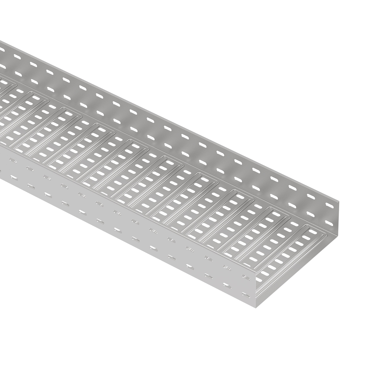
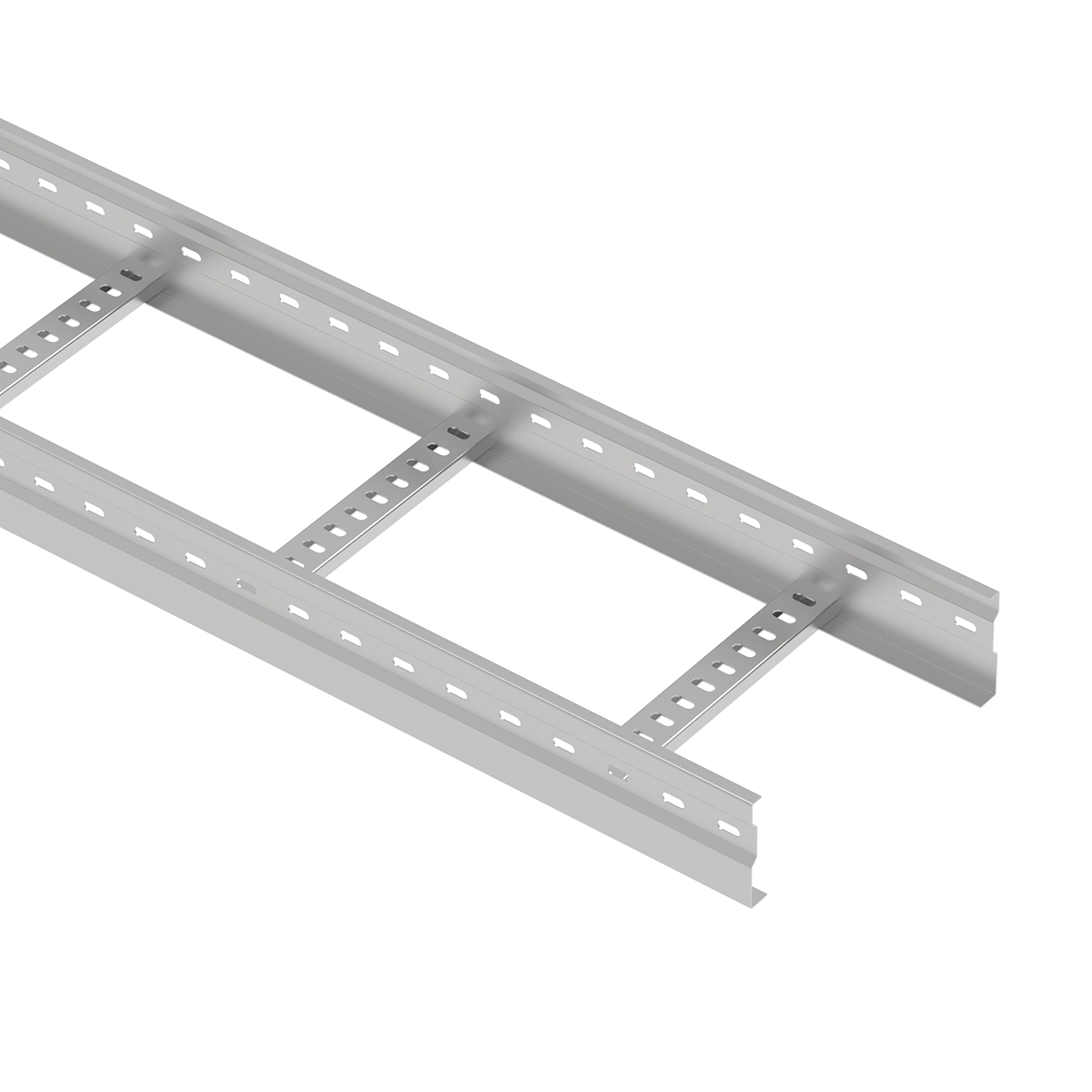
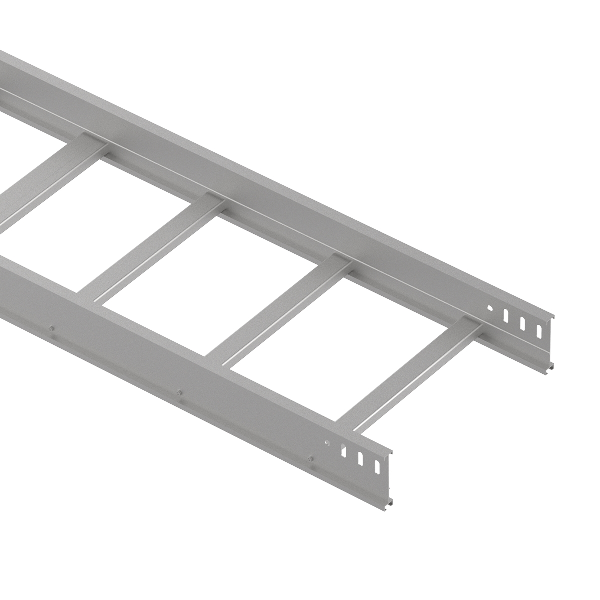
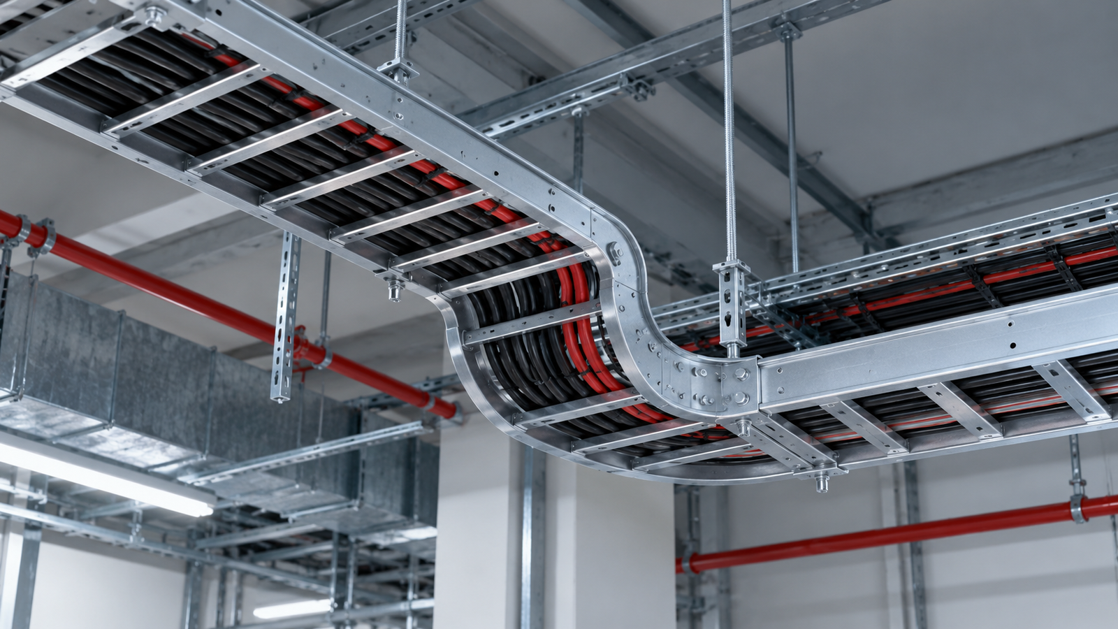
A cable tray span load class is useful only when it is read as a paired condition: how much uniformly distributed cable load a particular tray system can carry, and how far apart its supports are. A class printed on a catalogue page does not automatically apply to every width, material, installation or support spacing. If the supports on site differ from the rated span, the designer needs the manufacturer’s load-versus-span evidence for the actual configuration.
This distinction matters in a plant, data centre or infrastructure run because a tray can look substantial while its longest unsupported section is the limiting case. The correct question is not simply “Is this a heavy-duty tray?” It is “Does this exact tray configuration meet the required load and deflection limits at our installed support distance?” This guide explains how to read the classification, establish the load case and ask for the documents that make a specification defensible. It deliberately does not assign a NEMA class to any offered product: the available product material does not contain a verified model-specific class or test report.
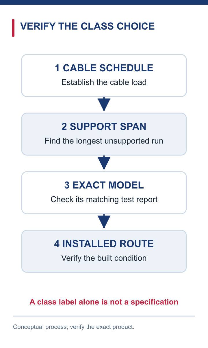
Conceptual guide; verify the project and exact product evidence.
In the NEMA VE 1 framework, the classification joins a support-span designation to a working-load designation. The Cable Tray Institute identifies VE 1 as the manufacturing standard that provides load/span class designations for metal cable tray systems. That is more informative than a free-standing claim of “high load capacity”, because it tells an engineer the conditions under which the classification should be checked.
Think of the class as the beginning of a specification, not its completion. It does not identify the mass of cables in a particular project; nor does it prove that every product in a manufacturer’s family has the same rating. A drawing may call for a class, while the selected model’s datasheet and test documentation establish whether that model actually meets it. Width, side-rail geometry, rung arrangement, material and finish can all vary between products. The exact model, tested configuration and support arrangement therefore matter.
A test or load table should also make clear whether its figure is a uniformly distributed load, a safe working load, or a failure load. These are not synonyms. A failure load is not an allowable service load, and a one-number claim without the span and deflection criterion leaves a vital part of the engineering decision unanswered.
A tray between two supports behaves as a spanning structural member. With the product and cable load unchanged, moving those supports farther apart changes the structural demand and the amount of deflection. That is why a load figure measured at one span cannot simply be transferred to a longer span. The engineer should seek a load-versus-span table or a calculation and test basis covering the installed spacing.
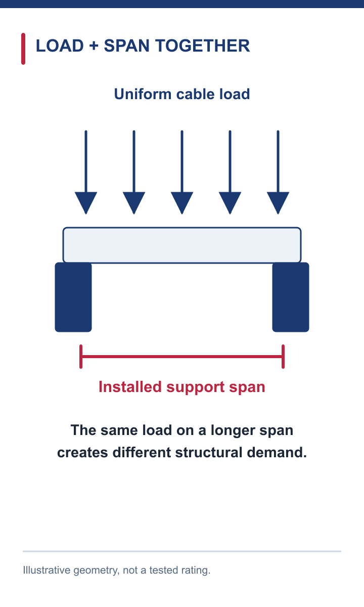
Conceptual guide; verify the project and exact product evidence.
In practice, start with the support layout, not with a preferred catalogue class. Mark the longest straight-run span and the locations of bends, tees, reducers and heavy local loads. A fitting or a concentrated load may require its own support rule; the uniformly distributed cable-load test should not be treated as proof for a technician’s weight or a heavy junction box at mid-span. Dynamic or seismic conditions also call for separate engineering checks.
Where the available documentation lists only one tested support distance, treat that as an evidence boundary. A shorter installed span may appear conservative, but do not infer a new published rating without the manufacturer’s method or table. A longer span particularly needs fresh evidence. Specify the maximum spacing explicitly so that an installer cannot inadvertently turn a valid paper selection into an unsupported arrangement on site. During inspection, measure the installed supports against the approved drawings rather than relying on the class label alone.
First identify which standard the project actually names. NEMA VE 1 is the source of metal cable-tray load/span class designations; IEC 61537 is another framework for cable tray and cable ladder system requirements and tests. A NEMA class and an IEC safe-working-load statement should not be presented as interchangeable certificates. The technical submittal must identify the applicable standard, test method, edition and exact system to which the result belongs.
A useful way to read a specification is to separate three questions. What performance does the project require? Which standard and loading arrangement define how that performance is assessed? Which product-specific report shows the selected tray meets it? The fact that two methods examine loaded spans does not by itself establish regulatory equivalence or certification for a named supplier model. Nor does a competitor’s published class transfer to another manufacturer’s products.

Conceptual guide; verify the project and exact product evidence.
Check the units carefully. Cable schedules often state mass per unit length, while test reports may state force or a total load applied over a span. Convert only when the underlying load definition is clear. A figure per metre and a figure for the whole tested length cannot be compared by matching their printed numbers. If a report uses a different span, cross-section or test method from the tender requirement, ask for a documented bridge or a more suitable report; avoid a verbal assurance that the two are “basically the same”.
The design load is a project input, not a property of the tray. Build it from the cable schedule for the specific route: identify each cable type, quantity and mass per metre, then add the planned allowance for future circuits or changes. Express the result per unit length so it can be compared with a tray-system load table on the same basis. If accessories or covers contribute materially, record how their weight has been treated.
Next separate uniform cable loading from unusual local conditions. Most standard class comparisons assume cable weight spread along the run. A large junction box, a worker load, a cantilevered section or equipment fixed to a rung changes the loading pattern. Those cases should be checked using a suitable manufacturer detail or project calculation rather than squeezed into the uniform-load number. The same caution applies at transitions and fittings, where straight-span behaviour may not describe the actual assembly.
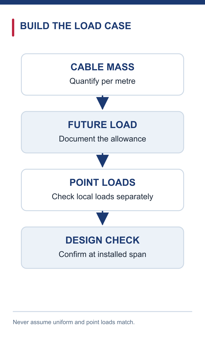
Conceptual guide; verify the project and exact product evidence.
Finally compare the design load with the product’s documented working limit at the selected support spacing and deflection criterion. Preserve the calculation assumptions: cable schedule revision, reserve allowance, support layout, product code, environmental conditions and the document revision used for the rating. A simple schedule with these fields is more reliable than a class letter detached from its source. If a required capacity is close to the documented limit, review the margin and potential future loading with the responsible engineer instead of assuming the word “heavy duty” supplies extra capacity.
Ask for evidence at the level of the exact proposed system. A practical submittal should identify the manufacturer and model code; material and finish; side-rail height and thickness; width; rung or bottom configuration; and any assembly details that affect how the specimen was tested. The test or calculation should name the standard and edition, the support span, the load application, the measured or permitted deflection, and the working-load result. Where the project depends on a particular class, the documentation should show how that class was established.
Check that the report and offered product agree. A report for one ladder width is not automatically a report for every width in a range. A result from a straight length does not by itself validate every bend, tee or connection. A laboratory identity and report number help trace the evidence, but the more important question is whether the tested specimen matches the product being supplied. Read the specimen description and the load–deflection data, not just the certificate cover.

Conceptual guide; verify the project and exact product evidence.
The installation instructions are part of this evidence chain. They should define support spacing and joint placement, and they should address the fittings and conditions that matter on the project. If an essential parameter is absent, mark it as an open technical question before procurement. Avoid filling a gap with a rating from another manufacturer or a generic rule of thumb: both could make the selection look documented when it is not.
The manufacturer presents cable tray and cable ladder systems for routing and supporting cables, and its existing load-capacity guide discusses the relationship between cable weight, support span and selection. That makes the company relevant to this decision. It does not, on the evidence available for this article, establish a particular NEMA load/span class for a named offered model. The two statements need to stay separate.
For a project enquiry, the useful starting point is a project schedule rather than an unsupported class assumption. Provide the required tray or ladder type, route width, cable load per metre, support layout, environmental conditions and the standard named in the specification. Ask the team to identify the exact candidate product and supply its matching span/load documentation, test basis and installation conditions. That request is a way to reach a verifiable answer; it is not a promise that every configuration will meet the requested class.

Conceptual illustration.
This article’s role is narrower than the manufacturer’s existing broad guide. It helps the reader interpret the class and scrutinise its evidence. Readers who still need to decide how to calculate cable mass or choose a general support span can consult the broader load-capacity guidance separately. Keeping those jobs distinct avoids repeating a general selection article and makes the final technical submittal easier to review.
For a cable tray span load class decision, record these six items in one place:
Then compare like with like. The manufacturer’s table or report must describe the offered configuration at the design span, not a different product or a shorter test span. If a number is a failure load, do not use it as the working limit. If a class is asserted without a traceable report, treat the rating as unverified until the missing evidence is provided. Put the accepted maximum support spacing on the drawing and verify it after installation.
The practical result of a cable tray span load class review is a selection that another engineer can trace: from cable schedule, to load case, to product, to tested or calculated capacity, to installed support layout. That chain—not the most impressive class label—is what makes a cable-management specification credible.