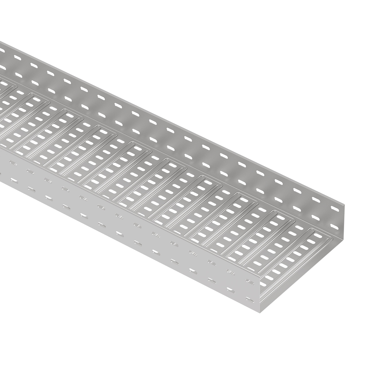
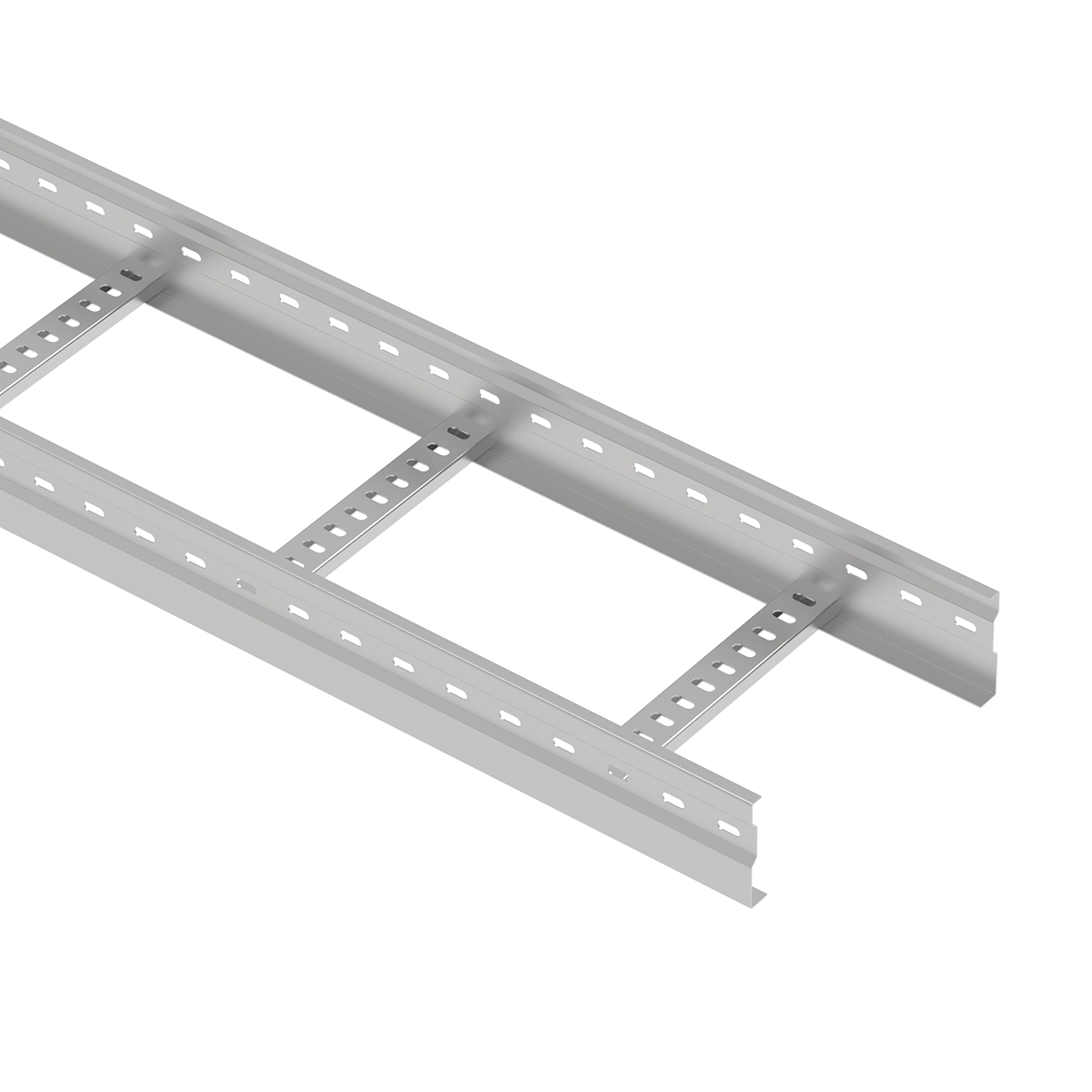
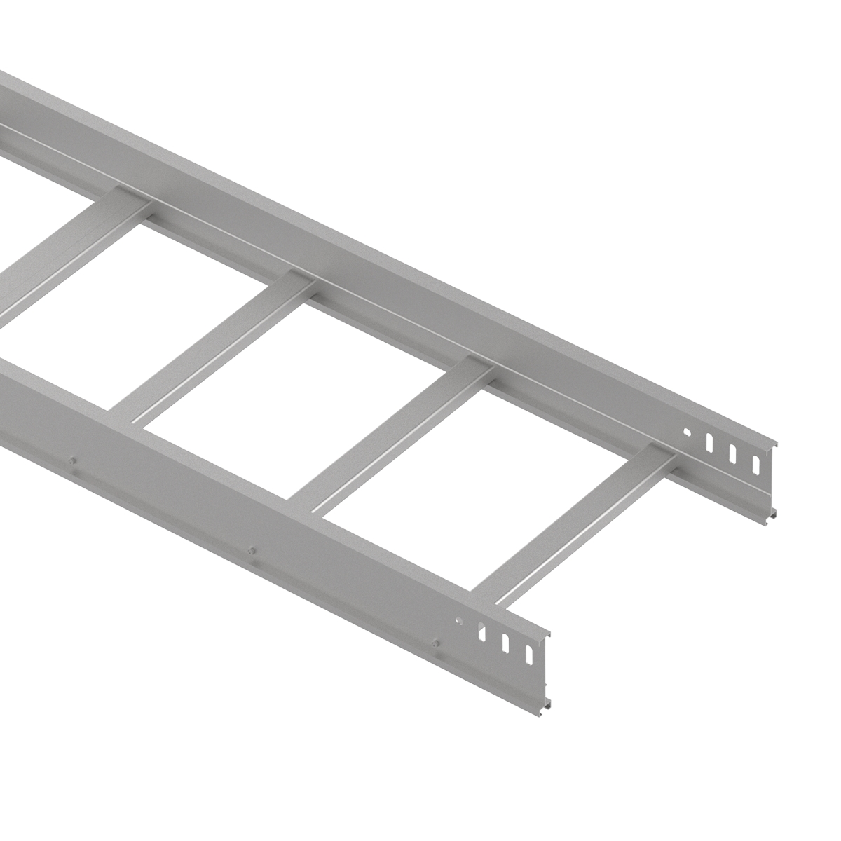
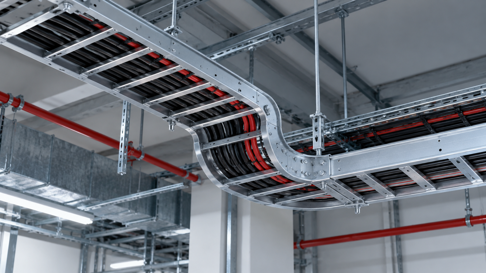
Perforated cable tray installation begins with a complete understanding of the cable route, loading requirements and supporting structure. Straight sections, joints, fittings and supports must work together to form a suitable cable pathway.
Correct installation involves more than securing trays at regular intervals. Support spacing must correspond to the selected configuration, connections must use compatible components, and the route must preserve cable bend radius and maintenance access.
This guide explains the main installation stages and the checks that help engineers, contractors and site teams make informed decisions. It covers preparation, supports, splice joints, field modifications, cable placement and final inspection.
Use the approved project drawings and product instructions for configuration-specific requirements. A general guide cannot establish fastening torque, joint position or support spacing for every perforated cable tray system.
The installation team should start with approved drawings, identified components and a defined support arrangement.
Resolve differences between the design and actual site conditions before fixing the route in place.
Compare the planned route with walls, columns, equipment and other building services.
Confirm elevations, direction changes, branches, equipment entries and penetrations. Leave sufficient access for laying cables, inspecting connections and removing covers.
Identify locations requiring additional coordination, such as building movement joints, outdoor transitions and fire-rated barriers. Firestop details must match the applicable tested or approved penetration system.
Record site conflicts and obtain the necessary design resolution before proceeding. Moving a tray around an obstruction can change support locations, fitting requirements and cable bending space.
Check delivered components against the approved specification and BOQ.
| Item | What to Verify |
|---|---|
| Dimensions | Width, sidewall height and straight-section length |
| Thickness | Specified base metal thickness |
| Bottom design | With or without stamped bottom reinforcement |
| Material | Required steel or stainless steel grade |
| Surface finish | GI, HDG, ZM or specified powder coating |
| Connections | Compatible splice plates and fastening assemblies |
| Fittings | Correct dimensions, angles and radii |
| Supports | Specified brackets, hangers and fixing components |
| Documentation | Relevant drawings, performance data and instructions |
Inspect components for distortion, damaged finishes and missing hardware.
Matching nominal dimensions do not guarantee compatibility. Different profiles can use different connections, covers or hole arrangements.
IEC 61537 specifies requirements and tests for cable tray and cable ladder systems. Installation should also follow the selected product’s instructions and applicable local electrical requirements.
Use cable manufacturer data to calculate cable weight per meter:
Cable load per meter = sum of each cable quantity × its weight per meter.
Include defined future additions and assess covers, accessories and other applicable loads.
Compare the required load with data for the selected tray configuration and support span. Confirm whether the published rating includes tray self-weight or represents additional payload.
The supporting assembly needs its own review. Brackets, rods, anchors and the supporting substrate must carry their design loads.
Where information is based on theoretical analysis, identify it as calculated data. Do not present it as a tested working-load rating.
A planned sequence makes inspection easier and reduces the chance of loading an incomplete route.
| Stage | Installation Task | Check Before Continuing |
|---|---|---|
| 1 | Inspect delivered components | Specification, condition and quantities |
| 2 | Set out the route | Elevations, clearances and interfaces |
| 3 | Install supports | Anchorage, alignment and spacing |
| 4 | Assemble straight sections | Joints, hardware and restraint arrangement |
| 5 | Install fittings | Cable radius and fitting support details |
| 6 | Complete permitted modifications | Finished edges, cleaning and surface treatment |
| 7 | Complete bonding and movement details | Required connections, gaps and guides |
| 8 | Inspect the empty tray route | Readiness for cable installation |
| 9 | Lay and restrain cables | Arrangement, load, bending and fixing |
| 10 | Complete final inspection | Deficiencies, records and as-built information |
Protect components during handling and storage. Avoid dragging coated surfaces or using damaged sections without assessment.
Qualified personnel should carry out installation under the applicable site work procedures.
Supports transfer cable and tray loads into the building or equipment structure.
Select them according to the route geometry, load, substrate and environmental conditions.
Wall brackets and cantilever arms can support routes alongside walls or columns.
Confirm the bracket capacity for the required projection and load position. For cantilever supports, the distance of the load from the fixing affects the demand on the bracket and anchorage.
Check the supporting structure, anchor type, fixing location and installation requirements. Do not assume that a wall is suitable simply because an anchor can be installed in it.
Align supports so the tray rests as intended without being forced into a twisted position.
Suspended arrangements may use threaded rods, channels and compatible attachment components.
Assess the complete assembly, including the structural fixing, rods, cross-member and tray restraint. Where multiple trays share one support, account for their combined loads and positions.
Level the assembly and provide lateral or seismic restraint where required by the design.
Do not attach the cable tray route to another service unless that support arrangement has been specifically designed and approved.
Floor-mounted supports should suit the substrate, route height and loading arrangement.
On rooftops, coordinate support details with the roof design. Review waterproofing, load distribution, attachment or ballast, material compatibility and applicable wind actions.
Maintain planned drainage paths and access. Support bases should not damage the roof surface or obstruct maintenance routes.
Cable trays and personnel walkways have different functions and require separate structural assessments.
Support spacing is a configuration-specific design parameter.
Review:
Product length is not support span. A 3000 mm section may require intermediate supports.
Do not apply a universal reduction factor for rooftop, corrosive or seismic locations. These conditions require assessment of the relevant loads, restraints and structural details.
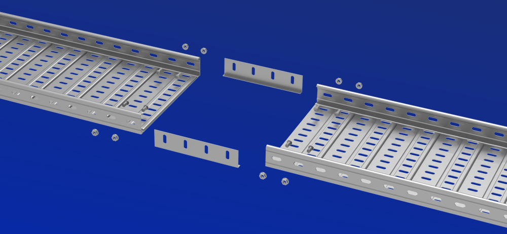
During perforated cable tray installation, verify joint compatibility and alignment before applying the specified fastening torque.
Position sections according to the route geometry and support arrangement.
Check alignment across the base and sidewalls. Confirm that splice plates seat correctly and connection holes match.
Do not use fasteners to pull significantly distorted sections together. Investigate uneven supports, damaged components or incompatible profiles first.
Recheck alignment after tightening. The finished route should not contain unintended steps, twists or projections that interfere with cable placement.
Use the connection components specified for the selected tray system.
| Connection Detail | What to Confirm |
|---|---|
| Splice plate | Correct profile, type and position |
| Fasteners | Size, grade and quantity |
| Washers and locking parts | Specified assembly |
| Hardware orientation | No harmful projections into cable space |
| Material compatibility | Suitable for the exposure and adjoining components |
| Electrical continuity | Required connection or bonding provisions |
Use the specified hardware rather than substituting locking washers, nuts or coatings without review.
Material compatibility is an assembly-level decision. Identical metals are not always necessary, but any combination must be appropriate for the environment and connection design.
Apply the torque and tightening procedure provided for the actual fastening assembly.
Bolt diameter, grade, coating, lubrication and joint construction affect tightening requirements. There is no universal torque value for all cable tray connections.
Use suitable tools and maintain calibration where the inspection procedure requires it. Do not add lubricant unless permitted by the fastening specification.
If hardware strips, distorts the sheet or fails to achieve the specified condition, inspect and correct the joint before loading the route.
Splice position can influence structural behavior.
Follow the manufacturer’s instructions and the connection arrangement underlying the relevant load data. Avoid generic rules such as placing every splice directly over a support or within one tray width of it.
Rigid joints and movement joints may have different requirements.
If the route requires a different splice position, review the change before installation rather than assuming the existing rating still applies.
Fittings need sufficient cable space and the support arrangement specified for their geometry.
Horizontal bends change direction in the horizontal plane.
Select the fitting radius and usable pathway to accommodate the cables’ installation and final bending requirements. Nominal tray width alone does not establish sufficient turning space.
Provide the prescribed fitting supports and maintain access around the bend.
For cable pulling, plan appropriate rollers and temporary arrangements without imposing unassessed loads on the tray.
Internal and external risers describe different directions of vertical curvature. They do not mean indoor and outdoor installation.
Use the fitting drawing to confirm the required orientation, radius and connection geometry.
At elevation changes, review cable bending, support positions and cable restraint. Vertical cable weight must be carried by the designed support arrangement rather than allowed to accumulate at a bend or termination.
Tees and crosses create branches. Reducers connect routes of different widths.
Check how cables divide and turn through each fitting. A branch can require more space than the adjoining straight sections.
At reducers, verify that the narrower section accommodates the remaining cables and their required arrangement.
Use compatible connection parts and the specified supports. A straight-section load rating does not independently establish the capacity of a branch fitting.
Fitting supports should follow approved details for the selected system.
Changes in direction can alter load distribution and introduce local demands. Confirm where supports are required and how the fitting connects to them.
Keep the route’s mechanical support separate from any additional cable restraint needed at vertical transitions or equipment entries.
Only carry out modifications permitted for the selected system.
Assess their effect on connections, reinforcement and protective finishes before cutting or drilling.
Confirm dimensions against fixed reference points and allow for the specified connection arrangement.
Check whether the cut affects formed edges, bottom reinforcement, connection holes or movement provisions.
Use tools suitable for the material and finish, following site procedures for sparks, debris and nearby equipment protection.
For stainless steel, use suitable tools and handling practices to limit contamination from carbon steel.
Remove sharp edges, burrs and metal slivers from permitted cuts and holes.
Where specified, install compatible edge protection or cable exit components. These should remain secure under the expected temperature, exposure and mechanical conditions.
Do not rely on loose trim to compensate for a poorly finished cut.
Remove swarf and other debris before cable installation. Inspect cable contact surfaces using suitable methods and protective equipment.
Apply the repair procedure appropriate to the substrate and coating.
GI, HDG, ZM and powder-coated steel may have different requirements. Do not assume one touch-up product is suitable for all finishes.
Follow the specified surface preparation, repair material, application and curing requirements.
For stainless steel, cleaning or other surface treatment may be necessary according to the fabrication procedure. Do not prescribe passivation or electropolishing automatically for every field cut.
Record repairs where required by the inspection plan.
Inspect the completed empty route before installing cables.
Confirm that supports, connections, edges and required bonding details are ready.
Place cables according to the approved schedule and routing layout.
Maintain the required grouping, separation and layer arrangement. Available physical space does not automatically permit additional cable layers or circuits.
Distribute cable weight in line with the assessed loading arrangement.
Secure cables without damaging their jackets. Record approved changes and update route identification so later maintenance uses accurate information.
Follow the cable manufacturer’s requirements for bend radius, pulling tension and other applicable installation limits.
Pulling forces can differ substantially from the final distributed cable weight. Plan rollers, pulling direction, equipment and temporary supports accordingly.
Do not use the tray as a pulling-equipment anchor unless that duty has been specifically assessed.
Where lubricants are proposed, confirm cable compatibility and suitability for the installation.
Choose restraints according to their required function.
| Function | Selection Consideration |
|---|---|
| Cable organization | Bundle size, jacket compatibility and accessibility |
| Vertical weight support | Cable weight, spacing and fixing capacity |
| Outdoor restraint | Temperature, UV exposure and environmental suitability |
| Short-circuit restraint | Assessed fault forces and suitable supporting evidence |
| Sensitive cable management | Bend radius and compression limits |
An ordinary cable tie used for organization should not be assumed suitable for vertical weight support or short-circuit restraint.
Verify that the restraint’s attachment to the tray is also appropriate.
Maintain access to joints, fittings, cable exits and equipment connections.
Allow covers to be removed and restraints to be inspected or replaced. Multi-tier routes should have a practical access strategy using suitable work platforms or other approved equipment.
Do not use the cable tray itself as a ladder or standing platform.
Review available space and structural capacity before adding cables later.
Mechanical assembly, electrical continuity and movement accommodation must be coordinated.
Bonding connects conductive parts as required by the electrical design. The protective earthing or grounding arrangement must provide the required fault-current path.
A connection to earth alone does not establish effective fault clearing.
Confirm whether the tray system and its connections satisfy the applicable requirements, and identify where dedicated bonding or protective conductors are needed.
Do not assume every metal tray can serve as a protective conductor.
Use approved connection details. Do not remove coatings, add jumpers or substitute hardware without following the relevant instructions.
Evaluate movement where route length, temperature variation or structural interfaces make it relevant.
The design may require expansion fittings, guides, fixed points or other movement provisions. Gap settings depend on the product and installation conditions.
Keep intended movement free from rigid fixings or cable arrangements that prevent travel.
Where bonding components cross a movement joint, they must accommodate the required movement while maintaining the specified electrical connection.
Covers are installed where the project requires them; they are not automatically necessary for every exposed route.
Review cover weight, access, thermal effects and retention under applicable wind conditions.
Use compatible clamps or fixing components and maintain required movement and drainage.
A cover does not automatically make perforated cable tray watertight or dust-tight. Cable and accessory suitability for the environment remains necessary.
Inspection should verify the installed configuration and resolve deficiencies before acceptance.
| Inspection Area | Checks |
|---|---|
| Product specification | Correct dimensions, thickness, material and finish |
| Route | Approved elevation, clearances and maintenance access |
| Supports | Correct positions, alignment and attachment |
| Straight sections | Condition, alignment and required restraint |
| Splice joints | Compatible plates, complete hardware and specified tightening |
| Fittings | Orientation, support positions and cable bending space |
| Field modifications | Permitted details, finished edges and debris removal |
| Surface protection | Damage assessed and required repairs completed |
| Cables | Arrangement, bend radius, distribution and restraint |
| Electrical continuity | Required bonding and specified verification |
| Movement provisions | Correct gaps, guides and unrestricted travel |
| Covers and dividers | Fit, retention and accessibility |
| Penetrations | Approved firestop or weather-sealing details |
| Records | Inspection results and updated drawings |
A visual inspection alone does not prove load capacity or electrical continuity. Complete the verification required by the project’s inspection and test plan.
| Mistake | Better Practice |
|---|---|
| Copying support spacing from another product | Use data for the selected configuration |
| Treating section length as support span | Specify both separately |
| Mixing incompatible splice components | Check profiles, connections and hardware |
| Applying a generic fastening torque | Use the specified assembly procedure |
| Placing every splice at the same relative position | Follow the system’s joint requirements |
| Ignoring fitting supports | Verify the relevant fitting arrangement |
| Leaving sharp edges or swarf | Finish and clean modifications before cable placement |
| Assuming a metal joint provides adequate bonding | Confirm the electrical continuity provisions |
| Fixing a movement joint rigidly | Follow the movement design |
| Adding cables without reassessment | Check both space and load |
| Using tray as personnel access | Provide separately designed access equipment |
ECTRAY manufactures perforated cable trays, fittings, supports and related accessories for industrial, commercial and infrastructure cable routes.
Available configurations include trays without stamped bottom stiffening and trays with stamped bottom reinforcement. Installation details should correspond to the selected geometry, material and performance basis.
Explore ECTRAY’s perforated cable tray range when preparing your specification.
For technical discussion or quotation, provide:
Planning a perforated cable tray installation? Send ECTRAY your route drawings, cable load and proposed support arrangement for technical discussion.
Use the spacing supported by the selected configuration’s performance data and installation instructions. Cable load, joints, fittings, supports and environmental actions can affect the arrangement.
Only where the required load and installation conditions are covered by the relevant data. Manufactured section length alone does not establish an allowable support span.
Follow the product instructions and the joint arrangement associated with the assessed performance. There is no universal location suitable for all tray systems.
Use the specified value and procedure for the actual fastening assembly. Bolt size, grade, finish, lubrication and joint construction can affect the requirement.
Permitted cuts can be made using the approved procedure. Check the resulting connection, finish the edges, remove debris and restore protective treatment where required.
Not necessarily. Some systems provide the required continuity through their specified connections. Other joints or interruptions may require additional bonding. Follow the electrical design and product instructions.
Only through an appropriately designed tray and restraint arrangement. Cable weight, fixing spacing, local attachment capacity and termination loads need assessment.
Not automatically. Local base stiffening does not independently establish overall working load or permitted span. Use configuration-specific evidence.
Do not use cable tray as a walkway or working platform unless it has been specifically designed and approved for that purpose.
Review cable arrangement, usable space, additional weight, tray capacity, supports, joints and electrical requirements. Record approved changes for future maintenance.