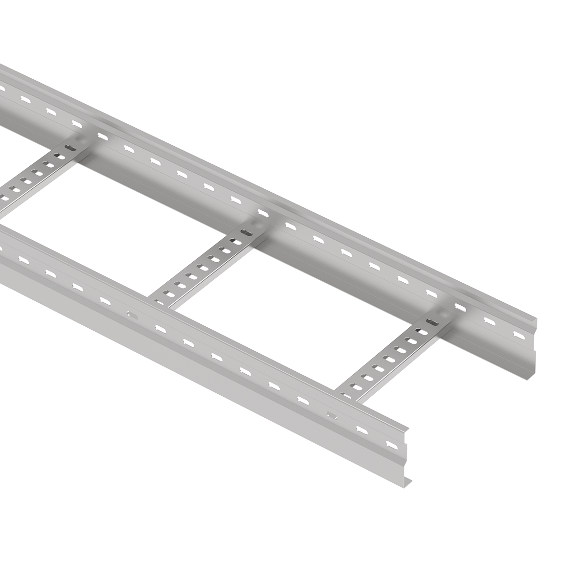
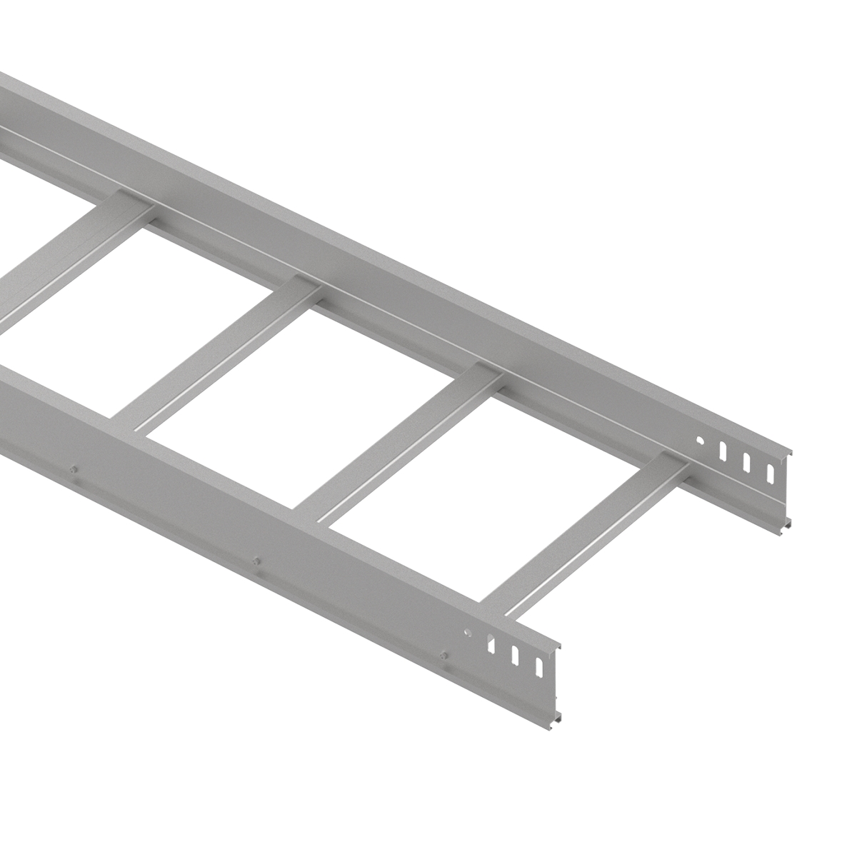
Cable ladder trays are open cable support systems constructed with two longitudinal side rails connected by transverse rungs. They are widely used to route and support power, control, instrumentation, and communication cables in industrial, infrastructure, power, and commercial projects.
Compared with more enclosed cable management systems, cable ladder trays provide high cable accessibility, efficient ventilation, flexible cable entry and exit, and strong structural performance for long cable runs.
Selecting the right cable ladder requires more than choosing a width or material. Engineers should also consider cable load, support span, side-rail height, rung spacing, corrosion conditions, installation environment, fittings, and future cable capacity.
This guide explains how cable ladder trays work, their main types and materials, how load and support span affect selection, common installation methods, accessories, applications, and the key information required when specifying a cable ladder system.
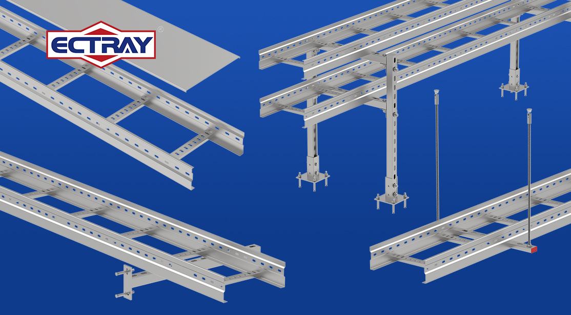
A cable ladder tray is a cable support system consisting of two side rails connected by regularly spaced rungs. The rungs support the cables while the open structure allows cables to enter or leave the route at multiple points.
Cable ladder systems are commonly selected for installations that require high cable capacity, long routing distances, accessible maintenance, or relatively heavy power cables.
A complete cable ladder system normally includes straight sections, bends, risers, tees, crosses, reducers, splice plates, covers, clamps, and structural supports.
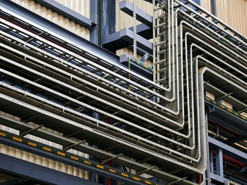
A cable ladder system is built from several structural and routing components:
Cable ladder trays distribute cable weight through the rungs to the side rails and then through the supporting brackets or frames to the building structure.
The performance of the complete system therefore depends on several connected factors:
Cable load → Rungs → Side rails → Support span → Support structure
A larger ladder does not automatically mean a higher allowable load. Structural capacity must be evaluated together with the ladder design, material, thickness, side-rail geometry, rung construction, and distance between supports.
This relationship becomes especially important in heavy-duty and long-span installations.
A cable ladder is one type of cable tray system. Its defining feature is the open construction formed by side rails and rungs.
Other common cable tray designs include perforated trays, solid-bottom trays, and wire mesh trays.
Cable ladders are generally selected where projects require:
Perforated or solid-bottom trays may be preferred where smaller cables require more continuous support or where additional physical protection is required.
Cable ladder systems can be classified according to structural duty, material, surface protection, and application requirements.
Standard cable ladders are used for general cable routing where cable loads and support spans remain within the verified capacity of the selected system.
They provide an open, accessible cable pathway suitable for many commercial, industrial, and infrastructure installations.
Heavy-duty cable ladders are designed for projects with higher cable loads, longer support spans, larger cable bundles, or demanding industrial conditions.
Their structural performance depends on factors such as side-rail profile, material thickness, rung design, connection strength, and support span.
For heavy-duty projects, selection should be based on verified load data rather than tray dimensions alone.
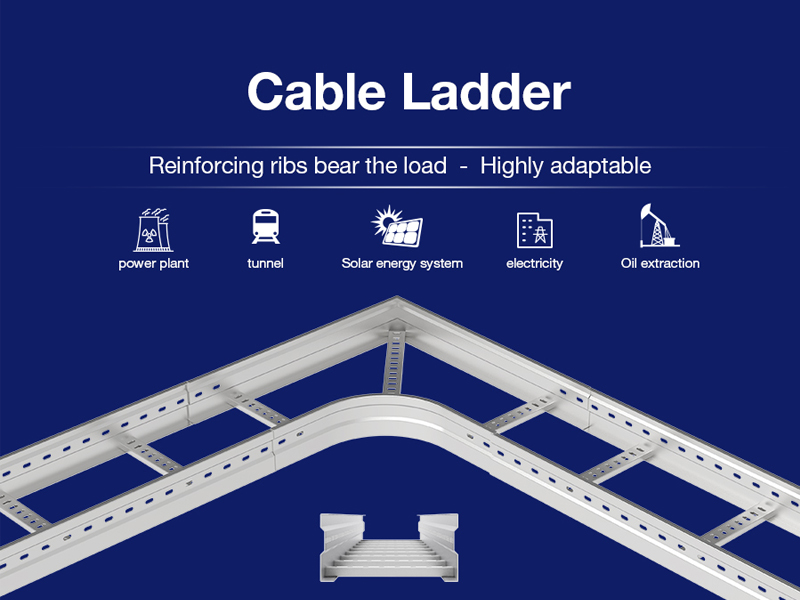
Aluminum cable ladders combine relatively low weight with good corrosion resistance, making them useful where installation weight, handling efficiency, and environmental exposure are important considerations.
Their lower weight can simplify transportation and installation, particularly for elevated cable routes.
However, material selection should still consider required load capacity, span, environmental conditions, and project specifications
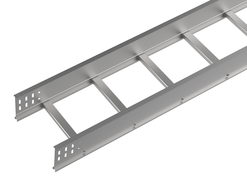
Steel cable ladders provide high structural strength and are widely used for power, industrial, infrastructure, and heavy-duty cable support systems.
Different surface treatments can be selected according to the installation environment, including GI, HDG, ZM, and powder-coated finishes.
For outdoor or corrosive environments, the required surface protection should be evaluated according to project exposure conditions and specifications.
Cable ladder trays are commonly selected for large-scale electrical installations because they combine structural support with open cable access.
The main advantages include:
The side-rail and rung structure can be engineered for substantial cable loads and longer support spans. Actual allowable load depends on the specific ladder design and support conditions.
The open construction allows natural air circulation around installed cables, which can assist thermal management where ventilation is important.
Cables remain accessible along most of the route, simplifying cable laying, inspection, maintenance, replacement, and future additions.
Cables can enter or leave the ladder at multiple points, while bends, tees, crosses, reducers, and risers allow the system to follow complex project layouts.
Open cable routes can make future cable additions and modifications easier, provided sufficient tray capacity has been considered during the original design.
Selecting between a cable ladder, perforated tray, solid-bottom tray, and wire mesh tray depends on cable type, cable load, support requirements, protection level, installation environment, and maintenance needs.
| System | Cable Load | Ventilation | Cable Access | Typical Use |
| Cable Ladder | High | Excellent | Excellent | Power, industrial and infrastructure |
| Perforated Tray | Medium–High | Good | Good | Power and control cables |
| Solid-Bottom Tray | Application-dependent | Limited | Moderate | Applications requiring continuous support |
| Wire Mesh Tray | Light–Medium | Excellent | Excellent | Data, communication and light power cables |
A cable ladder is generally preferred when structural capacity, cable accessibility, larger cable bundles, or longer cable routes are important project requirements.
Cable ladder trays are widely used in projects that require organized routing of large cable volumes, accessible maintenance, structural support, or long cable routes.
Used for routing power, control, and auxiliary cables in power plants, substations, and utility infrastructure where structural reliability and cable capacity are critical.
Suitable for factories and processing facilities with extensive electrical distribution networks and frequent maintenance requirements.
Cable ladders can support power and control cable routes in solar and other renewable-energy installations, particularly where outdoor durability and corrosion resistance are important.
Open cable ladder systems can provide accessible and scalable routing for selected power and communication cable infrastructure.
Cable ladders are used in airports, railway stations, tunnels, bridges, and other infrastructure where long cable routes and coordinated support systems are required.
Heavy-duty and corrosion-resistant cable ladder systems can be selected for demanding environments involving high cable loads, outdoor exposure, humidity, chemicals, or industrial contaminants.
Calculate the expected cable load per unit length and include any additional project loads required by the engineering specification.
Cable ladder selection should be based on verified system capacity rather than tray width alone.
Tray width depends primarily on cable quantity, cable diameter, spacing requirements, and planned future capacity.
Side-rail height also affects usable cable space and can influence structural performance.
Support span is the distance between adjacent structural supports.
Load capacity and support span must always be evaluated together. Increasing the span generally increases structural demand on the cable ladder.
Use manufacturer load data or project-specific calculations to confirm the selected configuration.
Rung spacing determines how frequently cables are supported along the route.
The appropriate spacing depends on cable type, cable diameter, cable weight, minimum bending requirements, and project specifications.
Closer rung spacing can provide more frequent cable support, while wider spacing may be suitable for cables capable of spanning greater distances between rungs.
Rung spacing should therefore be selected as part of the complete cable support design rather than as an isolated dimension.
Cable ladder load capacity cannot be determined from tray width or material alone.
The structural performance of a cable ladder system is influenced by:
For example, the same ladder section may perform differently when installed over different support spans.
For engineering selection, always evaluate load and span together and refer to verified manufacturer load data, applicable standards, or project-specific structural calculations.
Higher Cable Load + Longer Support Span = Greater Structural Requirement
For heavy-duty installations, engineers should confirm the required working load, support span, system configuration, and applicable safety requirements before finalizing the cable ladder specification.
Cable ladder material and surface protection should be selected according to structural requirements, corrosion exposure, installation environment, service life expectations, and project specifications.
GI steel offers a cost-effective solution for many indoor and controlled-environment cable support applications.
HDG provides enhanced corrosion protection for steel cable ladders and is widely considered for outdoor, industrial, and infrastructure environments.
ZM coated steel combines structural steel performance with enhanced corrosion protection and can be considered for demanding outdoor and industrial applications, subject to project requirements.
Stainless steel provides high corrosion resistance. SS316 is generally selected for more demanding coastal, chemical, and corrosive environments.
Aluminum provides low weight and good corrosion resistance, helping reduce handling and structural dead load.
Powder coating provides a finished surface and additional environmental protection for selected indoor or specified applications.
Proper installation is essential for maintaining the structural performance and reliability of a cable ladder system.
Key installation considerations include:
Supports should be positioned according to the ladder system design, load requirements, manufacturer recommendations, and applicable project specifications.
Adjacent ladder sections should be properly aligned and connected using the specified splice plates and fasteners.
Bends, tees, crosses, reducers, and risers should be adequately supported and positioned to maintain cable routing requirements.
Cable fixing, segregation, spacing, and routing should follow the applicable electrical design and project requirements.
Long cable ladder routes may require provision for thermal expansion depending on material, route length, temperature range, and installation conditions.
Grounding and bonding requirements for metallic cable ladder systems depend on the electrical design, tray construction, connection method, local electrical code, and project specifications.
Where electrical continuity is required, joints, fittings, and connections should be installed using the specified bonding components or conductors.
The cable ladder should not be assumed to function as a grounding conductor unless the complete system has been designed, installed, and approved for that purpose under the applicable requirements.
For detailed installation procedures, see our Cable Ladder Installation Guide.
A complete cable ladder system may include:
Fittings allow cable routes to change direction, branch, transition between sizes, or adapt to structural conditions.
Accessory selection should match the ladder width, side-rail height, material, surface finish, route geometry, and installation requirements.
Read more: Cable Ladder Accessories and Fittings Guide.
Before requesting a quotation or finalizing a specification, confirm the following information:
| Specification | Project Information |
| Material | Steel / Aluminum / SS |
| Surface Finish | GI / HDG / ZM / Powder Coating |
| Width | 200-1000mm / 8 ~ 39 in |
| Side-Rail Height | 50mm/100mm/150mm/200mm 2 in/4 in/6 in/8 in |
| Length | 2000mm/2500mm/3000mm/6000mm 79in /98in/ 118in / 236 in |
| Material Thickness | custom made |
| Rung Spacing | custom made |
| Support Span | Typically evaluated at 1.5–3.0 m depending on cable load, ladder dimensions, material, thickness and project requirements. Heavy-duty or longer spans should be confirmed using verified load data or structural calculations. |
| Installation | Indoor / Outdoor |
| Environment | Normal / Coastal / Industrial / Chemical |
| Fittings | Bend / Tee / Cross / Riser / Reducer |
| Cover | Required / Not Required |
| Applicable Standard | -- |
| Project Quantity | -- |
A cable ladder tray is an open cable support system consisting of two side rails connected by transverse rungs. It is commonly used to support and route power, control, instrumentation, and communication cables.
They are widely used for industrial, power, infrastructure, data center, renewable-energy, and other large-scale electrical installations requiring accessible cable routing and structural support.
Consider cable quantity, cable diameter, cable load, required separation, future cable capacity, side-rail height, and available installation space.
There is no single load value for all cable ladders. Capacity depends on ladder design, material, thickness, side-rail geometry, support span, and system configuration.
A heavy-duty cable ladder is designed for higher structural demands such as heavier cable loads, longer support spans, or demanding industrial installations.
Typical solutions include trapeze supports, wall brackets, cantilever supports, C-channel systems, threaded-rod suspension systems, and customized structural supports.
The correct material depends on structural requirements and environmental exposure. Common choices include GI, HDG, ZM, stainless steel, and aluminum.
Grounding and bonding requirements depend on the metallic tray system, electrical design, applicable code, and project specification.
Yes, provided the material and surface protection are appropriate for the actual outdoor environment and project requirements.
Covers may be specified where cables require additional protection from falling objects, weather exposure, contaminants, or other environmental conditions.
Selecting a cable ladder system requires balancing cable capacity, structural load, support span, material, corrosion resistance, route configuration, installation environment, and future expansion requirements.
For standard installations, tray dimensions and material may be sufficient starting points. For heavy-duty, long-span, outdoor, industrial, or infrastructure projects, load performance and support design should be reviewed together as part of the complete cable support system.
ECTRAY provides cable ladder, fittings, and support systems for power, industrial, transportation, renewable-energy, data center, and infrastructure projects. Project-specific dimensions, materials, surface finishes, fittings, and support configurations can be selected according to engineering requirements.
Preparing a new project? Send us your BOQ, cable load, support span, drawings, or specification for technical review and quotation.

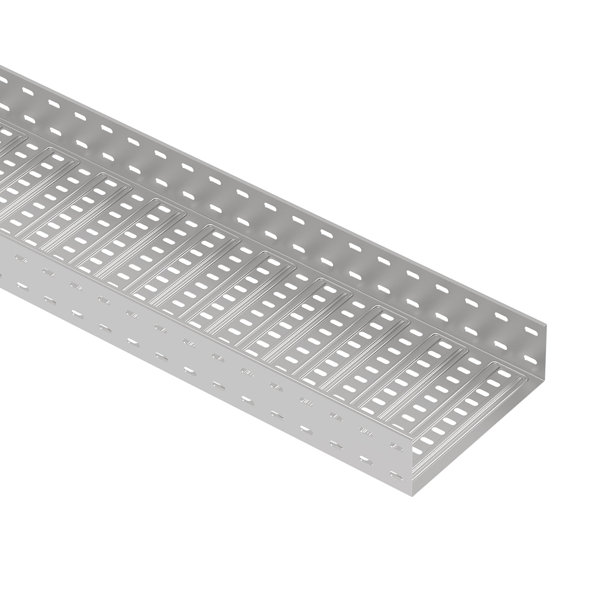
[…] For broader product selection, see ECTRAY's cable ladder selection guide. […]