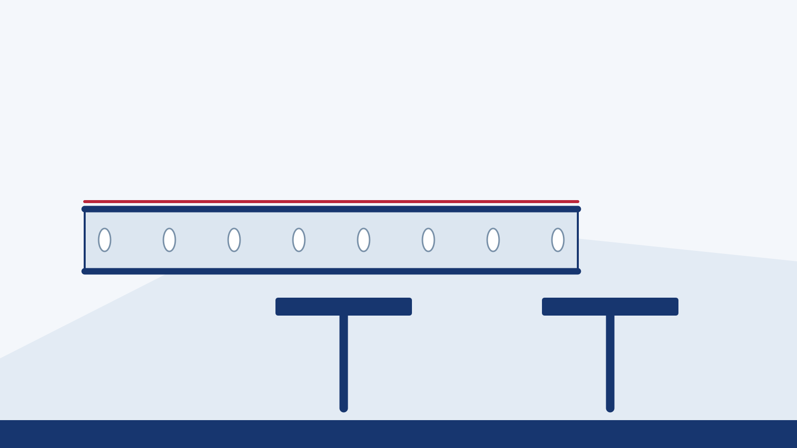
Solar cable tray systems organize and support cable routes between photovoltaic arrays, combiner boxes, inverters and associated electrical equipment. Their selection involves more than choosing a tray width or surface finish. The cable arrangement, installation environment, support structure and maintenance requirements all influence the final specification.
For rooftop solar projects, the system must also coordinate with roof drainage, waterproofing, equipment access and structural limitations. For ground-mounted projects, route elevations, outdoor exposure and transitions between equipment areas require careful planning.
This guide explains the main components of solar cable tray systems and provides a practical selection process for engineers, EPC contractors and procurement teams.

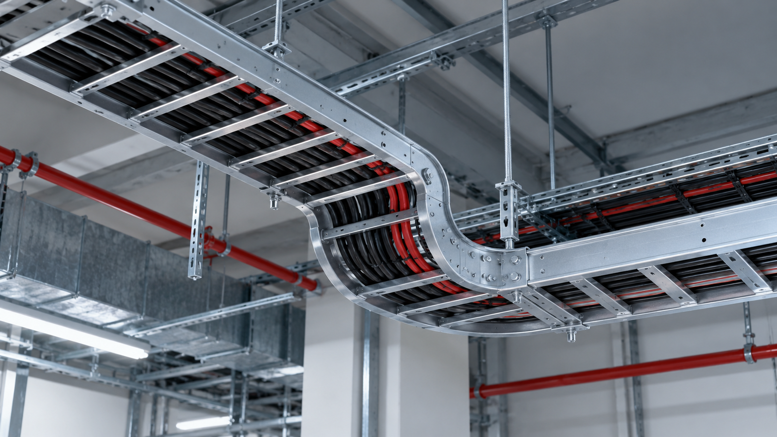
A solar cable tray system is an assembly of cable support products, fittings, connections and supports used along designated routes within a photovoltaic installation.
Its suitability depends on the complete arrangement. A tray section, splice plate and rooftop support should be selected as compatible parts of the specified system.
Rooftop installations need cable routes that fit around module rows, roof equipment, drains and maintenance areas. Changes in elevation and entry points into buildings or equipment enclosures should be planned before installation.
Ground-mounted projects may involve longer routes between array zones and electrical equipment. The layout needs to account for the available supporting structures, site conditions and transitions to other cable installation methods.
The permitted cable types and installation methods must be confirmed against the applicable electrical requirements and project specification.
The complete supply can include considerably more than straight tray sections.
| Component | Function |
|---|---|
| Perforated cable tray | Supports cables along the selected route |
| Cable ladder | Supports cables on spaced rungs |
| Bends and risers | Accommodate horizontal and vertical direction changes |
| Tees and crosses | Form branch connections |
| Reducers | Connect different route widths |
| Splice plates and fasteners | Join compatible sections |
| Supports and brackets | Transfer system loads to an approved supporting structure |
| Covers and clamps | Provide the specified cover arrangement |
| Dividers | Separate cable groups where required |
| Bonding components | Provide the specified electrical continuity arrangement |
Prepare the component schedule alongside the route drawing. This helps identify missing fittings and interfaces before purchasing.
Solar cable tray systems can use different support types in different route sections. Selection should follow the cable requirements and available product data.
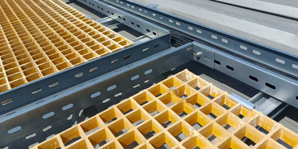
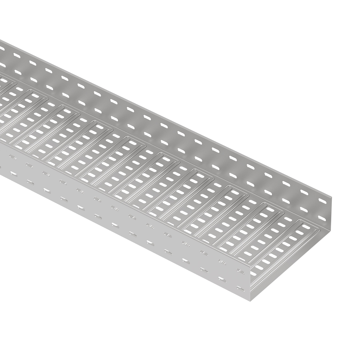
A perforated tray provides a base with openings for cable support and routing.
ECTRAY offers designs with and without stamped bottom reinforcement. Reinforced designs are available in sheet thicknesses from 0.6 to 1.5 mm.
The reinforcement profile and sheet thickness should be specified together with the tray width, height and material. The presence of reinforcement alone does not establish the allowable load at a particular support span.
Explore ECTRAY’s perforated cable tray range when preparing the product specification.
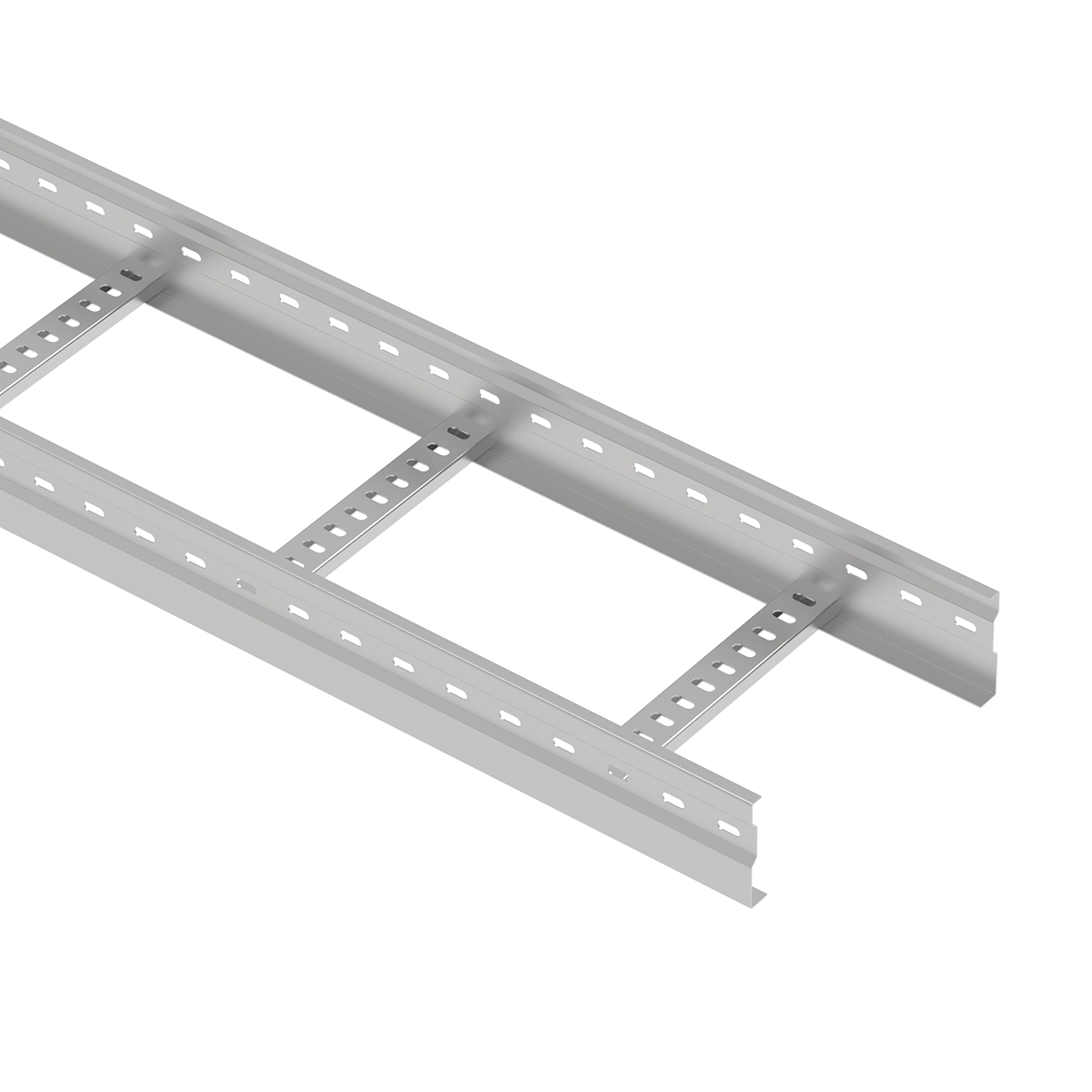
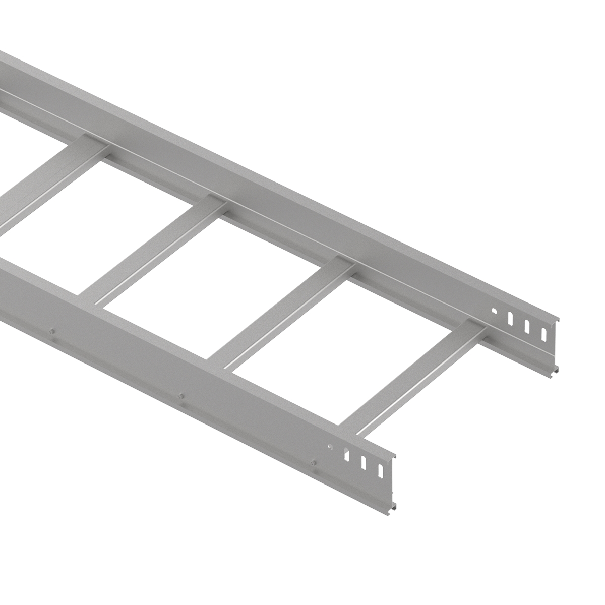
Cable ladder supports cables on spaced rungs.
When evaluating this option, check whether the selected cables are suitable for the proposed rung spacing and restraint arrangement. Cable entry, exit and vertical transitions also need appropriate support.
Do not assume that every ladder configuration has a higher load capacity or longer allowable span than every perforated tray. Compare documented performance under equivalent conditions.
ECTRAY’s steel cable ladder can be reviewed alongside perforated tray options for the relevant route sections.
Covers should be selected for an identified project requirement.
A cover changes the system configuration and introduces additional considerations, including its weight, fixing arrangement, inspection access and potential effects on cable thermal conditions.
A covered tray should not automatically be treated as a sealed enclosure. Confirm the intended protection and the suitability of the complete assembly.
Material selection should begin with the actual exposure conditions.
Identify whether the route is indoors, sheltered, fully exposed, coastal or subject to industrial contaminants. Then review the tray, supports, fasteners and accessories together.
GI, HDG and ZM describe different coated steel options. They should not be treated as interchangeable specifications.
| Option | Description | Information to confirm |
|---|---|---|
| GI | Pre-galvanized steel | Coating specification, fabrication details and suitability for the exposure |
| HDG | Hot-dip galvanized after fabrication | Applicable coating requirements, inspection and repair procedures |
| ZM | Zinc-aluminum-magnesium coated steel | Coating designation, product documentation and application suitability |
| Powder-coated steel | Steel with a specified powder coating system | Substrate preparation, coating system and damage repair method |
| Stainless steel | Specified grade, such as 304 or 316 | Grade suitability, fabrication condition and environmental exposure |
Avoid specifying a coating only by its commercial name. Include the relevant material and coating requirements in the purchasing documents.
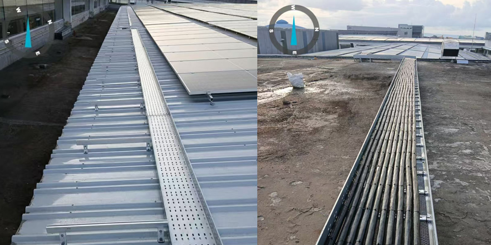
Where stainless steel is considered, confirm the required grade against the project environment and specification.
The review should include fasteners, supports and connection components. Selecting a stainless steel tray while leaving the remaining components unspecified can create an incomplete system definition.
Corrosion resistance should be assessed for the actual exposure rather than expressed as a universal service-life promise.
Review material compatibility throughout the assembly.
The tray, splice plates, bolts, clamps and supports may experience different exposure and contact conditions. Confirm suitable combinations and any required isolation details.
Maintenance access and the ability to inspect or replace components should also inform the selection.
Sizing should begin with the cable schedule and route layout.
Width, height, sheet thickness and support span answer different questions and should be specified separately.
Prepare a cable schedule containing cable type, quantity, outside diameter and weight per unit length.
Confirm how the cables will be arranged and whether separation is required between different circuits or functions. Review cable manufacturer requirements and the applicable electrical design criteria.
Future additions should be based on the project expansion plan. Avoid applying an arbitrary spare-capacity percentage to every installation.
Tray width should accommodate the approved cable arrangement. Height should be reviewed alongside usable internal space and the selected profile.
Sheet thickness contributes to the product configuration, but thickness alone does not establish load capacity.
For reinforced perforated trays, record the selected thickness within the available 0.6–1.5 mm range. The manufacturing range should not replace an exact order thickness.
For an initial cable weight schedule, calculate each cable group separately:
Cable weight per metre = cable quantity × individual cable weight per metre
Add the cable groups to obtain the total cable weight per metre.
This provides one input to the mechanical review. It is not a complete design load.
The system assessment should also address tray self-weight, covers, accessories and applicable environmental or other project loads. Check how the manufacturer’s load information accounts for these items.
Select the support span using relevant performance data for the actual tray configuration and installation conditions.
Rooftop solar cable tray systems must coordinate with the building and its maintenance needs.
The route drawing should identify both where the cables travel and how the system is supported.
Map module rows, inverter locations, roof penetrations, drains and other rooftop equipment before finalizing the route.
Allow access to equipment and roof features that require inspection or maintenance. Avoid layouts that obstruct drainage or create unnecessary crossings.
At equipment entries, coordinate the transition from tray support to the specified enclosure entry method.
A rooftop support arrangement needs an approved method of transferring loads to the building.
Depending on the project, this may involve structural attachments, approved clamps or an engineered non-penetrating arrangement. No single support method is suitable for every roof.
Confirm structural capacity, local load effects, waterproofing compatibility and the applicable roof warranty requirements.
The tray supplier’s component information should be coordinated with the project’s structural and roofing decisions.
Outdoor routes may require assessment for wind and other location-specific loads. Covers and supporting components should be included in that review where applicable.
Long routes also need consideration of thermal movement. Expansion arrangements, fixed points and guided supports must work together.
Manufacturer guidance illustrates that expansion provisions depend on factors such as run length and temperature difference. Use the instructions applicable to the selected system rather than a universal expansion-joint spacing.
Cable trays and solar maintenance walkways serve separate functions.
The tray supports cables. The walkway provides a designated access route where specified for the project.
Plan them together so technicians can reach equipment and inspect the cable route without placing cables across the walking surface.
Cable trays should not be treated as walkways unless a separate, specifically designed and approved arrangement establishes that function.
Installation should follow approved drawings, applicable requirements and the instructions for the selected products.
A general blog cannot establish project-specific support spacing, bolt torque or electrical bonding details.
Confirm the support positions and joint arrangement before installation.
Use compatible splice plates, fasteners and fittings. Review transitions and changes in direction so cables remain appropriately supported.
Where field cutting or drilling is permitted, follow the specified edge treatment and coating repair procedures.
Check the cable manufacturer’s bend-radius and handling requirements.
Provide suitable support at changes in direction, vertical transitions and equipment entries. Restraints should be appropriate for the cable, exposure conditions and required mechanical performance.
Do not rely on the tray outline alone to confirm that the installed cables have the required bend radius.
Confirm the required electrical continuity and bonding arrangement for the complete metallic system.
Expansion connections, discontinuities and particular joint types may need additional provisions. Follow the approved electrical design and product documentation.
Do not assume that every metallic tray is automatically suitable for use as a protective conductor.
A practical inspection record should cover:
These records help document the installed configuration for handover and future inspection.
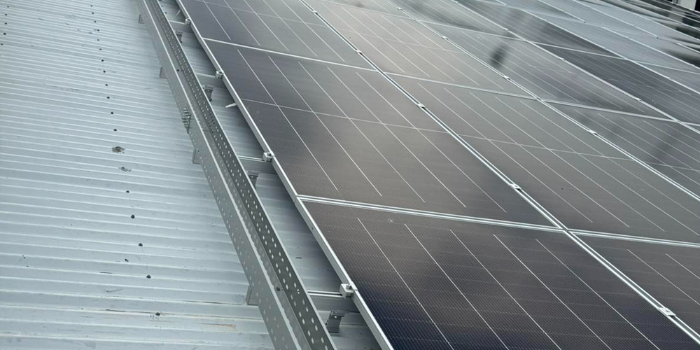
ECTRAY’s Philippines rooftop solar project supply included 7,000 metres of HDG cable trays and 1,000 sets of O&M walkways.
This project illustrates the value of coordinating cable management and maintenance access within the same overall rooftop layout.
The project quantities describe the supply scope. Dimensions, support arrangements and performance requirements for a new project should be confirmed independently.
Visit ECTRAY’s project case studies to explore additional application experience.
A clear request for quotation helps suppliers define the product and identify outstanding engineering information.
| RFQ item | Information to provide |
|---|---|
| Project location | Country, site and relevant exposure conditions |
| Installation area | Rooftop, ground-mounted or equipment area |
| Roof information | Roof type and approved support interface where applicable |
| Route drawings | Lengths, elevations, turns, branches and equipment entries |
| Cable schedule | Cable types, quantities, diameters and weights |
| Product type | Perforated tray, ladder or a combination |
| Dimensions | Width, height and section length |
| Thickness | Exact required thickness or information needed for selection |
| Material and finish | Grade, coating and relevant specifications |
| Load and span | Cable loading, proposed supports and applicable project loads |
| Accessories | Covers, fittings, dividers, splice plates and fasteners |
| Documentation | Drawings, material records and relevant performance information |
| Delivery | Quantities, packaging requirements and delivery schedule |
Compare quotations on the complete supply scope. A lower straight-section price may exclude supports, covers, fittings or documentation included elsewhere.
ECTRAY supplies cable trays, cable ladders, supporting components and solar O&M walkway products for project-based procurement.
For solar cable tray systems, share your cable schedule, route drawing, installation environment and support requirements. These inputs help clarify the required configuration and matching accessories.
Start with the project conditions, then confirm the tray, finish, supports and connection details as a coordinated system.
They organize and support designated cable routes within photovoltaic installations. The permitted cables and installation methods must be confirmed against the applicable project requirements.
The choice depends on cable support needs, route conditions, restraint requirements and documented load performance. Different sections of one project can use different systems.
There is no universal choice. Review exposure conditions, material specifications, component compatibility, maintenance access and project requirements.
No. Covers should be selected for a defined requirement. Their weight, fixing, thermal implications and maintenance access should be reviewed as part of the system.
The available sheet thickness range is 0.6–1.5 mm. Specify the exact thickness required for the selected configuration.
Use relevant product performance information and the approved project design. There is no single spacing suitable for every tray, load and roof arrangement.
Cable trays support cables and should not be treated as walking surfaces. Provide a separately specified maintenance walkway where access is required.
Provide route drawings, cable information, dimensions, material and finish requirements, proposed support conditions, accessories and quantities.