Comparing cable tray sizes is not a matter of picking one number. A buyer may see a nominal width on a price list, while the installer needs to know the clear space between the sidewalls, the height available above the cable-bearing surface, the length of each straight section and the outside envelope that has to fit through the route. None of those measurements proves that the tray will carry the planned cable load at the proposed support spacing.
Start with the route's cable schedule and the permitted arrangement of those cables. Use it to determine the space needed now and for documented future circuits. Then compare that requirement with a specific manufacturer's dimension drawing, loading data and compatible fittings. This order prevents a familiar mistake: selecting a wide tray because it looks spacious, only to discover that its usable depth, bend geometry or working-load rating does not suit the installation.
This guide is a method for narrowing a specification, not a substitute for the adopted electrical code, the project engineer's design or the selected product's instructions. It covers perforated, ladder and other tray forms where the distinctions matter. A published size chart can help create a shortlist, but the final choice belongs to the exact cable set and route.
The common shorthand is width × sidewall height × straight-section length. That notation is useful for comparing cable tray sizes across catalogue families, but it leaves several engineering questions unanswered. Does “width” mean the external dimension, the distance between the rails, or a nominal designation? Is the quoted height measured from the underside of the base, the top of a rung, or another reference? Is the straight-section length the manufactured length rather than the permissible distance between supports? A drawing should settle each point.
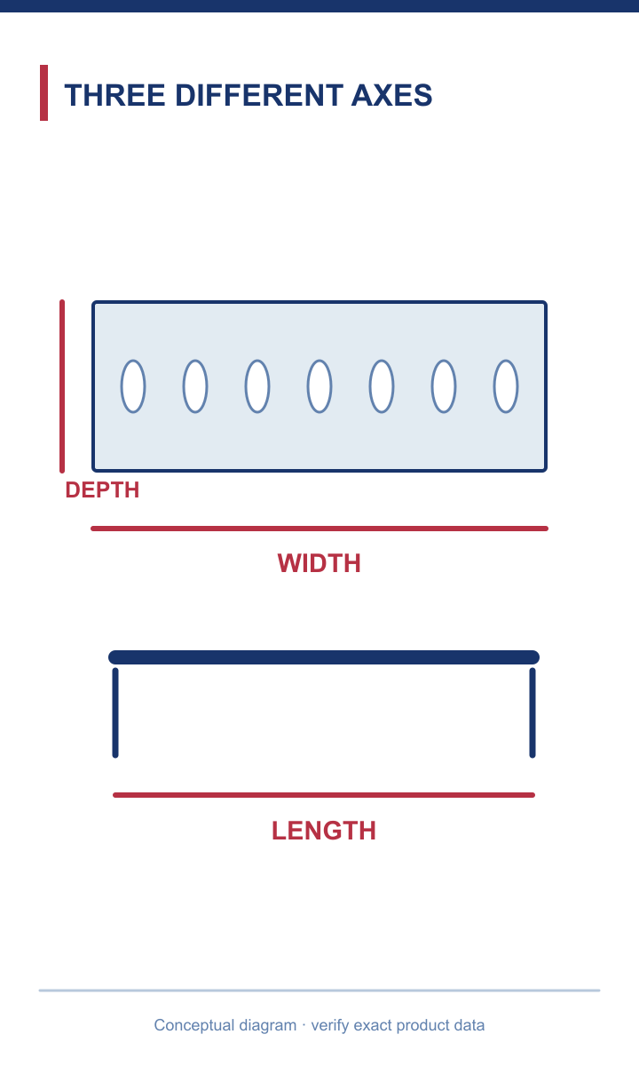
Dimension arrows separately show tray width, side height and supplied section length.
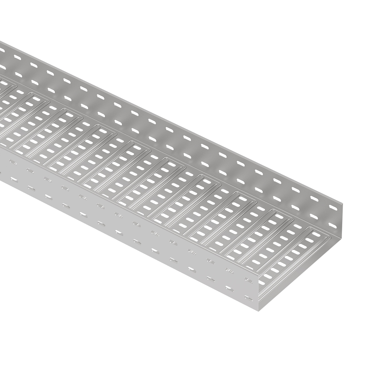
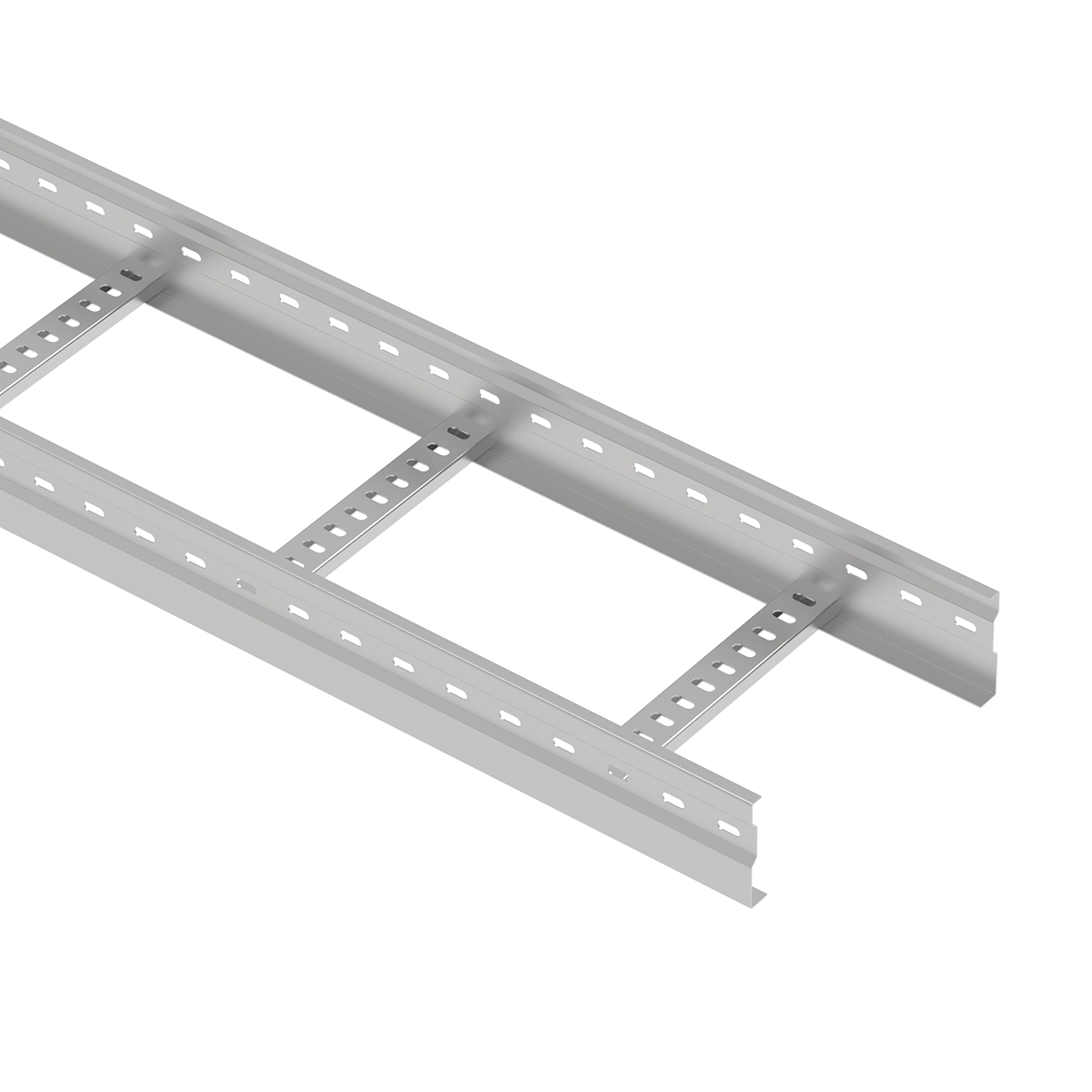
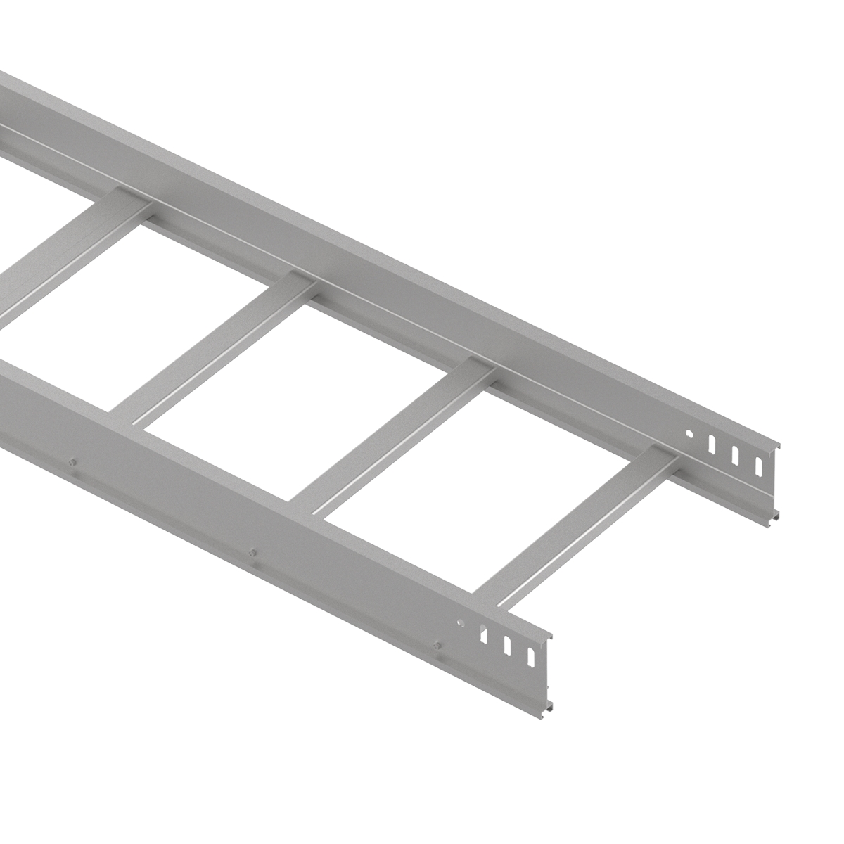
For a perforated tray, check the clear width inside its formed sides and any lips or returns. For a ladder, check the space between rails and the loading depth above the rungs. A divider may reduce the space available to each cable group, even when the overall tray width is unchanged. The outer envelope matters separately when the run passes a beam, rises through a shaft or must leave room for a cover and installation access.
Length describes the section that will be delivered, handled and joined on site. It influences the number and location of splices and the fit around access constraints. It is not a load class. Keep a second line in the schedule for the permitted working load at the intended support span; ask which configuration and test basis the figure describes. A useful size schedule therefore includes both the physical dimensions and the performance and arrangement information needed to use them.
Imagine two trays both advertised as 300 mm wide. One supplier may use 300 mm as the outer dimension; another may use it as a nominal product series. Rail thickness, rolled returns, splice hardware or a divider can make their clear spaces different. This is why a width printed in a catalogue should not be turned directly into the number of cables that fit. The cable layout should be checked against the clear dimensions on the drawing for the chosen configuration.
The same caution applies to depth. Side rail height is a convenient selection label, but cable loading depth can be measured from the bearing surface to a different point. On a ladder, a rung profile occupies part of that cross-section; on a perforated tray, a cover, fixing detail or edge return can change the effective space. Extra rail height does not automatically permit another cable layer if the relevant code, cable design or project specification requires a particular arrangement.
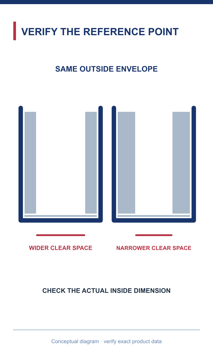
Equal outer labels flank two different inner clearances and make reference points visible.
Record both references in the procurement schedule: nominal product designation and verified usable inside dimensions. Record the outside dimensions too when spatial coordination is tight. These are not redundant figures. One checks catalogue compatibility, one checks cable placement, and the other checks whether the installed system clears neighbouring services. If a tender offers a substitute product, comparing those three measurements prevents a superficially similar item from changing the actual layout.
| Dimension to confirm | What the drawing must show | Decision it supports |
|---|---|---|
| Nominal product width | The manufacturer's designation and reference points | Comparing product families and fittings |
| Usable inside width | Clear distance available to the cable arrangement | Physical cable fit and separation |
| Usable loading depth | Height above the cable-bearing surface | Permitted cable layers and cover clearance |
| Outside envelope | Widest and highest installed points | Route and neighbouring-service clearance |
| Straight-section length | Manufactured length and splice location | Handling and joint planning, not support-span approval |
List the cables that will occupy each run, not merely the total number of circuits in the project. For every cable group, record type, quantity, outside diameter, weight per unit length, anticipated route, and any permitted or required arrangement. A cable with the same conductor size as another can have a different outside diameter or mass because its construction and insulation differ. A count of “twenty cables” is therefore not enough to size a tray.
Separate known future circuits from a vague wish for spare capacity. If a project has a documented expansion phase, include those cables in the layout or reserve a specifically agreed space for them. If the expansion is uncertain, state the design allowance and its basis rather than silently adding a universal percentage. Check where circuits join or leave the main route; the busiest section, not the average straight run, may govern the selected width.
Next, identify how cables may be placed. Large power cables may have a required single-layer layout, grouping or separation rule; control and communication cables can have different conditions. The adopted electrical code and cable manufacturer's requirements govern the actual arrangement and fill calculation. Do not assume that a single area percentage applies to every cable type or tray style. Sketch the cable cross-section using outside diameters and any separation, fastening or access allowance required by the project. That drawing turns the schedule into an observable width and depth requirement.
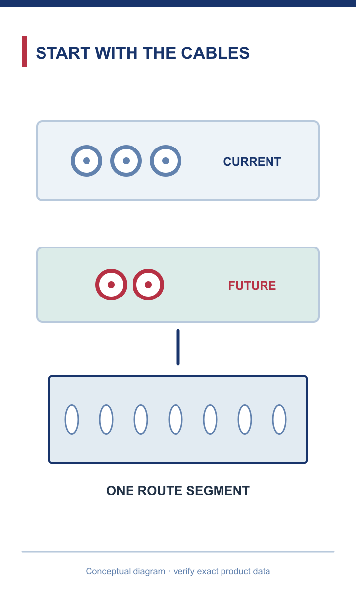
Cable groups and a documented future group feed the route arrangement before a tray is chosen.
Finally, total the mass per metre of the proposed cable arrangement. Keep that mechanical calculation alongside the physical layout. A layout may fit yet be too heavy for the selected support span. Conversely, a high-rated tray may be stronger than needed but still too narrow for the permitted cable placement. Width, depth and load are connected decisions, not interchangeable shortcuts.
Begin with the permitted cable arrangement, then compare it with the clear internal width. For a single-layer layout, place the specified outside diameters side by side, including the project-required spacing and any partition. For an arrangement where more than one layer is permitted, check the usable loading depth and the conditions that allow stacking. A simple cross-sectional area calculation can be a preliminary screen, but it does not show whether a large cable can make a bend, whether groups have to be separated, or whether an installer can reach and fasten the cables.
The best size is not necessarily the smallest catalogue option that produces a positive remainder on paper. Select a candidate that also accommodates the intended installation method and documented future additions. If the layout only fits by pressing cables against a rail return or placing a divider where no fitting can continue it, it has failed the practical test. Move to a different width, depth, tray type or route arrangement and document why.
Depth must be evaluated with the same care. A higher sidewall can provide a different containment and structural profile, but the usable cable-loading space and the working-load data still belong to the exact product. For a covered system, check the space beneath the cover and the fastening detail. For a ladder, compare the cable arrangement with the rung support and cable bend requirements. For a perforated tray, check the formed base, drainage or ventilation needs, and whether the selected fitting preserves the required support through a turn.
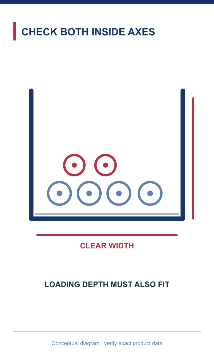
A tray cross-section shows permitted cable rows within both clear internal axes.
Use a table in the design record with columns for cable group, required arrangement, calculated occupied width, required usable depth, candidate tray drawing and unresolved assumptions. That table makes a later change traceable. If a new cable is added, the engineer can see whether the constraint is width, depth, heat, support capacity or route geometry rather than simply ordering the next wider tray.
A single-layer requirement is about where the cables sit, not merely how much area they occupy. A tray with generous depth does not solve an insufficient clear width when a set of cables has to lie side by side. Similarly, combining power and control cables into one geometric total can hide a required divider or separation distance. Draw the permitted arrangement at the congested sections and review it against the adopted rules before selecting a nominal size.
Grouping also changes what happens at branches. A divider that works in a straight section needs compatible tees, reducers and bends, or a documented way for the separated groups to continue through the change in direction. If one group exits earlier, a reducer may be appropriate, but the remaining cable arrangement and loading have to be checked after the transition. The dimension that governs a route can therefore change from one segment to the next; a single tray size across the whole project is convenient only if the engineering checks still pass.
Do not use an online calculator as the sole authority for this step. Calculators can be useful for a particular cable type and jurisdiction, but they often implement narrow assumptions about cable size, layer count or fill method. Keep their inputs and rule basis with the calculation. The value of the tool is a reproducible check, not a blanket declaration that every cable schedule fits a particular tray width.

Grouped routes split through a branch while maintaining distinct cable paths.
The tray has to support the installed cables, its own mass and any applicable project loads across the real distance between supports. A larger nominal width does not, by itself, establish a higher working-load rating. Different rail profiles, base forms, material thicknesses, splice details and support conditions can produce different performance even when the dimensions look similar. Select from the manufacturer’s published or submitted working-load information for the proposed configuration.
Record the planned support spacing from the building structure rather than assuming it equals the straight-section length. Then compare the declared allowable load at that span with the design loading. Check how the manufacturer treats joints, concentrated loads, fittings and any cover. If the relevant load table does not cover the intended arrangement, ask for a compatible system or a revised support layout. A destructive test result and an allowable working load are different figures; do not quote one as the other.
The support check may send the design back to an earlier step. Shorter spans can change the tray system that meets the mechanical requirement, but they also increase the number of supports and the installation work. A stronger profile may preserve a needed longer span but increase the outside envelope or self-weight. Where the building cannot accept a support at the intended point, the answer is not to assume the next wider tray is strong enough. Recalculate against the actual support positions and the manufacturer's data.
Document the decision as a pair: cable arrangement fits the usable dimensions, and calculated loading fits the verified working-load rating at the chosen span. A buyer should be able to trace both statements to a drawing, cable schedule and load table. If any input changes, such as an added cable or moved support, review both statements again.
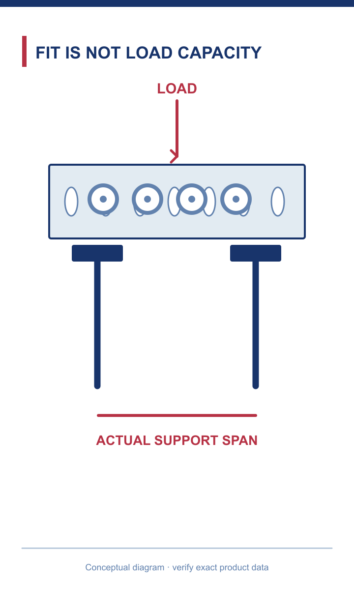
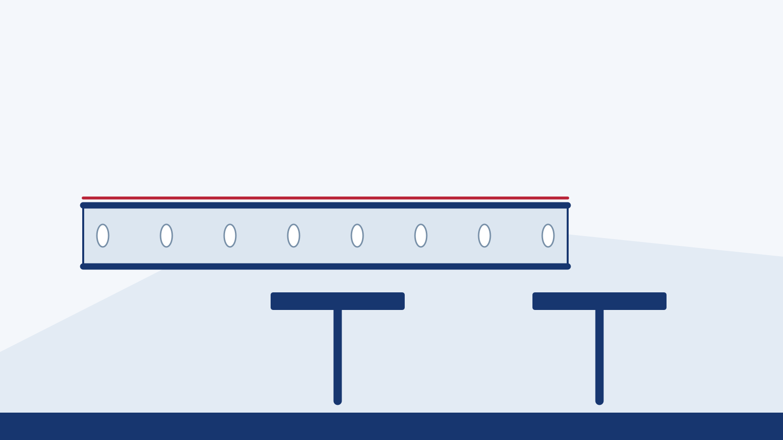
A loaded tray between supports illustrates why mass must be checked at the actual span.
Straight lengths rarely make a whole route. Bends, tees, crosses, risers and reducers must match the selected tray family and carry the intended cable arrangement through changes in direction. A bend with the same nominal width may still have a different overall footprint or internal path. Check cable minimum bending requirements against the fitting geometry, particularly for larger power cables and routes with tight equipment access.
The outside envelope matters at crossings, shafts, ceiling voids and equipment entries. Add the required space for brackets, covers, fastening, inspection and future work. A tray that fits the cable section but cannot be installed or opened is not an adequate size. The issue is especially visible at reducers: the narrower downstream section must be checked against the cables that remain, not merely against the upstream tray label.
Coordinate supports and joints with the fitting layout using the manufacturer's instructions and the structural design. Do not copy a universal support distance from a general article. Some systems have special support requirements near fittings or splices; other details depend on the actual load class and connection. Verify continuity and bonding requirements for the installed system separately from the tray's physical dimensions.
A route mark-up should show the governing clearances, candidate tray width and height, fitting types, support points, access side and any transition in cable population. This is useful information for procurement as well as installation. It reduces the chance that straight trays are ordered in the correct nominal size while fittings, covers or supports arrive in incompatible sizes or finishes.

A plan-view route identifies a bend, a reducer, supports and the outside envelope.
ECTRAY's heavy-duty perforated tray page shows a family of widths, side heights, lengths and compatible fitting types. That makes it a starting point for a project shortlist, not a guarantee that every size, material, finish and load combination is interchangeable. Ask for the current drawing and product data for the exact proposed configuration. Confirm the usable inside dimensions, outside envelope and available fittings before carrying a catalogue label into the design schedule.
For the proposed route, provide ECTRAY with the cable schedule, required arrangement, cable load per metre, support spacing, route geometry, installation environment and any project-specific documentation requirement. Request the working-load evidence for that configuration and span, plus the fitting and support details that keep the system consistent. The product page describes configurable thickness and finish, so neither should be inferred from width alone.
If a project calls for a cover, divider, reducer or alternative finish, check that the selected option remains available in the chosen dimensions. Where a particular standard or test report is required, match its scope to the specified model rather than treating a general certificate or a different configuration as proof. This keeps the article useful for buyers without converting manufacturer options into unsupported performance claims.
The same handoff discipline applies to any supplier. State the duty and constraints in measurable terms, then ask the supplier to identify a matching model and evidence package. That gives the engineer a basis for checking substitutions and gives procurement a way to compare quotations on more than nominal width or price.

A tray sample, product drawing and cable schedule are shown as distinct procurement objects.
First, divide the installation into route segments with distinct cable populations. Mark the busiest points, branches, changes of level, restricted clearances and planned additions. A calculation for a quiet straight run cannot govern a congested tee or riser without checking it. Keep the latest cable schedule version with the tray decision so the physical and mechanical inputs remain traceable.
Second, write down the proposed cable arrangement for each segment. Confirm the adopted electrical rules, cable bending and grouping requirements, any separation between services, and the project's future-capacity assumption. Calculate occupied width and required usable depth from that arrangement. Use a product drawing to compare the result with clear dimensions; do not substitute nominal or outer dimensions silently.
Third, calculate cable mass per unit length and add the other loads that apply to the installation. Determine actual support points and check the candidate system's working-load data at that span. Review splices and fittings in the same system. If the supplier cannot document a required combination, resolve it before procurement rather than leaving the installer to improvise a support or substitute component on site.
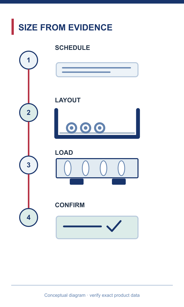
Cable schedule, arrangement, load-span check and exact product confirmation form an ordered design path.
Finally, issue a purchase specification that names tray type, material and finish, nominal and usable dimensions, straight-section length, required fittings, support arrangement, load basis and documentation. Attach route drawings and the cable schedule. Ask the supplier to identify any exceptions explicitly. A quotation with only “300 mm cable tray” does not tell the team whether the offered product fits the cables, carries the load, meets the exposure requirement or can be assembled into the intended route.
Do not treat a generic chart of cable tray sizes as a design. A chart may show what one manufacturer offers or what is common in one market, but it does not know your cable outside diameters, local rules, available supports or environmental exposure. Two pages can quote different “standard” widths without either list controlling a particular project. Use charts to identify candidate product families, then verify the specific drawings and test data.
Do not choose width and ignore depth, or choose depth and ignore the permitted arrangement. Avoid treating a fixed fill percentage from an unrelated calculator as universal. If a large cable must lie in one layer or two groups need separation, a simple area calculation can falsely suggest that a narrow deep tray works. A cross-sectional layout and the correct rule basis reveal the difference.
Do not assume that a longer supplied section authorizes a longer support span, that a higher sidewall proves a load class, or that a wider tray can carry more weight. Do not use a product-family certificate as proof for every configuration. Each of those shortcuts skips a different check. The safe result is a short, reviewable chain of evidence: cable schedule, permitted arrangement, usable dimensions, load at span, compatible fittings and exact product documentation. When that chain is complete, the tray size is a defensible specification rather than a guess.

A generic nominal chart is contrasted with a route-specific cable and support drawing.